The instrument works. It's playable, the action is reliable, and it even sounds pretty good for a first attempt.
So, with that said, I declare this blog finished, apart from a few final posts to summarize things I've learned, present a few concluding thoughts, display a slideshow of all photos of the construction process, plus (soon) a few audio tracks of the instrument being played.
Thursday, December 31, 2009
Final adjustments
In the past two months, I've continued along the lines suggested by the previous post, partly restringing the back 8' register in the lower regions and voicing the whole instrument down a bit. As was the case for the front 8', this has changed things for the better. Both rows of jacks now play well and repeat reliably.
With the overall strength of voicing altered, I tweaked the separation between both rows of jacks by revisiting the jack end screws. I ended up giving each another half-turn, so the back 8' now sits beneath the strings by the equivalent of 4 half-turns, and the front 8' by 8 half-turns. This gives a tiny bit more slack to the mechanism.
It's important to recognize that the primary means of controlling the interaction of the two registers when both are turned on is by means of consistent voicing, and not indiscriminate cranking of these end screws. The screws are meant to adjust how long it takes for the plectrum to rise up and contact the string from beneath. There may be small differences here and there due to the quill angle in the tongue, which are a result of the quill mortise punching process, and an extra half-turn or two of the end screws can correct for this, but that's the extent of their usefulness.
Friday, October 30, 2009
More debugging
I've been working on and off with the Trasuntino for the past two months, trying to get a handle on the troublesome repetition in the tenor and bass regions. What stymies me is that the jacks work perfectly well in the upper two-thirds of the instrument, yet they become troublesome about an octave below middle c'. No harpsichord will repeat perfectly right down to the bottom of the keyboard, but my problem areas are much too high up for me to feel completely comfortable playing the instrument.
After soliciting suggestions from the harpsichord list, I learned something very interesting that pertains to my difficulties. In a nutshell, the longer a string is, the thicker it must be in order to maintain a reasonable amplitude of vibration. "Reasonable" in this case means an amplitude that is not difficult to damp out when the jack comes back down. If the amplitude can't be controlled, repetition will be compromised.
The list experts reviewed my stringing schedule and a consensus developed that the schedule was too light in the lower regions by at least one, if not two, gauges. Several suggestions were offered that advised me to end with gauge #1 in the lowest regions (0.020"). One maker said that anything less than this would behave like a "loose clothesline". Since heavier wire must be under greater tension to reach the correct pitch, the resulting increase in stiffness means the wire won't flap around as much when vibrating.
Part of my stringing problems stemmed from a slight misunderstanding of mine regarding how stringing by numeric progression works. The original instruments on which this was practiced had keyboards extending up to d''', and starting higher by those extra two notes would allow heavier gauges to be used by the time one reached E in the bass. The Trasuntino only goes up to c''', which means I finished with gauge #3. I should have started with 9 strings of #9, and not 10, in order to get the correct results.
The new schedule has the crossover points between gauges occurring on higher notes than the current schedule. In adjusting the stringing to conform to the new schedule, there will be minor changes in the alto and treble, while the lower part of the instrument will require extensive restringing.
The changes higher up are so minor that I decided not to bother with them: besides, this isn't the problem area. So I applied the new schedule only from c' downwards. Because the crossovers occur higher up in this region, I was able to recycle a lot of existing wire by removing strings and tuning pins together, shortening each string slightly, and reinstalling it about a fourth higher. By reusing wire, I saved myself the trouble of depleting my wire supply, and also gained the advantage of using wire that has already stretched out over many months and developed its tone.
From F# downwards, new wire in gauges #2 and #1 was required. Since the numeric progression rule dictates that 2 wires of #2 and 1 of #1 are called for, there wouldn't be enough to reach C unless I wanted to use even thicker gauges , and excessively thick wire has its own problems (it can sound dull or otherwise strange). So I bent the rule by using 3 of #2 and 4 of #1. The short-octave note GG/BB was left unaltered, as it was originally strung quite heavily (.022" red brass).
I tried this schedule out on the front 8' at the beginning of October, and found that the stiffer wire did indeed improve repetition noticeably, without completely curing the problem. I decided to give the new wire several weeks to settle down and develop its tone.
Now, at the end of October, I've concluded the new wire sounds good, so I'll keep the changed schedule. Recently I've been revoicing the plectra in the restrung region, as they are not so well matched to the new wire. My sense of the register as a whole is that my initial voicing back in August was too heavy, so I went ahead and thinned all the quills in the entire register. With a lighter touch, the repetition has improved even more, to the point that I think the problem is almost cured. Next, I'll do the same to the back 8'.
Amplitude and string vibration have a more crucial effect on the playability of a harpsichord than I initially suspected. Originally I thought that, provided the scale was correct for the intended pitch level, one could string a harpsichord with purely sonic considerations in mind, but I now see that the mechanical reliability of the action is impacted by the string schedule too.
Thursday, September 10, 2009
Debugging phase
Construction of the harpsichord is essentially done. Only the music desk remains to be made at some point.
The harpsichord has been playing since the end of August. I'm now in a kind of debugging phase in which I play the instrument and track down things that need improvement. So far I have
The harpsichord has been playing since the end of August. I'm now in a kind of debugging phase in which I play the instrument and track down things that need improvement. So far I have
- increased the depth of touch about 1/32" by substituting a thinner cloth for one of the two layers under the jackrail
- shimmed up the keys with more punchings at the balance pin to help increase the depth of touch
- moved both of my gap spacers which, despite my best efforts, had not been located exactly under the strings and were slightly rubbing the nearest jacks
- tweaked the off positions of the registers to make sure the plectra cleanly miss the strings
- glued little cloth squares between the registers so they don't touch themselves or the edges of the gap
- done a little remedial voicing to quills that feel stiffer or sound louder than their neighbours
The main outstanding issue to be resolved is the troublesome repetition of notes in the bass. In this region the amplitude of the plucked strings is large. Damping can be problematic as a result, and the tongue is often flung backwards quite energetically when the jack descends and the plectrum touches the string. So I am experimenting with damper shapes, stiffer springs and various other factors in an effort to resolve this problem.
Monday, August 31, 2009
Dampers
Dampers are installed after the preliminary voicing, as it is easier to see the quills without them.
Dampers come in the form of a strip of felt about 1 cm wide and several feet long. A portion is pushed into the damper kerf of the jack and cut off from the back, leaving the damper a bit long. To determine the correct length, the damper is trimmed from the front while the register is in the off position (i.e. further from the string). If the damper sits on the string in this position, it will also work in the on position (closer to the string).
It's important that the dampers not be excessively long in the off position; otherwise, when the register is turned on, the damper may reach past its own string and damp a neighbouring one. This also means the register's off position cannot have the plectra too far away from the strings, otherwise by the time the register reaches the on position, the dampers may be too close to a neighbouring string.
I'm using so-called flag dampers, which are more or less square in shape and flat along the bottom edge. These dampers allow the jacks to hang slightly from the strings, which makes transposing the keyboard easy. If the jacks actually sat on the keys, the resulting weight and friction might interfere with transposition.
The bottom edge of these dampers should be just slightly above the tip of the plectrum. This little bit of slack keeps the action reliable during changes of humidity.
Voicing
Voicing, in the context of harpsichord-making, refers to the cutting of plectra (also known as quills) in a manner that draws forth a musically enjoyable sound from the instrument and feels controllable to the performer's fingers.
The same term is also used to describe the adjustment of organ pipes after manufacture. Unlike organ voicing, however, the voicing of harpsichord plectra cannot fundamentally transform the sound of the instrument. The tone is largely determined by various construction factors and the stringing materials, not by how plectra are cut. Volume and touch can be affected, along with the degree of shrillness, but not much more.
Historically, raven and goose feathers were the preferred materials for quill. Today, real quills are still used by some makers, while many others use Delrin or Celcon plectra. Both of these are hard, slippery plastics that have a long working life. They don't sound exactly like real quill, though they can get close if worked on by a knowledgeable voicer.
The process begins with ghosting, or setting the silences. Jacks are placed into all register slots, black delrin plectra are installed into all tongues, and the side-to-side position of the register is adjusted until the tongues are about 5 mm from the strings. The plectra are then trimmed from the tip until they just brush the strings when the jack is raised, without actually plucking in the normal manner, though in the bass they are allowed to weakly pluck the strings to adjust for the wire thickness. This process yields a consistent plectrum length of around 5 mm. As each quill is trimmed, the tip (as viewed from the side) is given a chisel-shaped profile to assist the backward tilt of the tongue when the jack descends.
Next, the register is advanced forward so that the plectra project past the strings by about one string diameter. This is the correct "on" position. The correct "off" position is set slightly behind the position at which the plectra ghost the strings.
With the register turned on, the tongue springs in each jack are adjusted so that the tongue tilts back as the jack descends. The severest test is to let the jack down extremely slowly: if the plectrum doesn't get hung up on the string, then the jack will work properly in every playing scenario. If the spring is too firm, stopping the tongue from tilting adequately, the tongue spring is bent back slightly and tested until the jack descends reliably.
Voicing can now begin. The intention is to produce plectra that pluck the strings consistently but not so strongly that the tone is harsh. To the fingers, the plectrum should be neither too firm nor too weak. A gradation in touch from bass to treble is required. The bass needs stronger quills because the string feels like it stretches somewhat before it gets plucked, due to the deeper plucking point in this region. In the treble, the short strings and close plucking point makes things feel stiff, so a weaker quill is needed.
This process can be expedited by using quills of differing thicknesses. Before ghosting, I experimented with 8 different quill thicknesses, discovering where it helped to change from one thickness to the next. I erred on the heavy side, since of course a heavy quill can be thinned to maker it weaker, but nothing can be done to strengthen a weak quill. Ultimately I used 6 different thicknesses, changing approximately every tritone to a thinner quill.
Voicing requires controlled cuts on the sides, arrises and underside of the quill, all of which thin the quill and reduce its stiffness. When done sensitively, the resistance of the quill as it raises the string seems to yield slightly just before the pluck, which I find feels quite controllable to my fingers.
The customary tools for voicing are shown below:

A set of wire cutters helps to trim excessively long plectra from the back. The hemostat acts like a set of pliers for installing and removing quills. Either a #11 scalpel blade (shown above) or a #11 Xacto knife blade are used for cutting the plectra. A voicing block—in this case the hard end-grain surface of an ebony block—acts as a little cutting board.
Once both registers received their preliminary voicing—a lengthy process that took two days of on and off work—the jack end screws were adjusted to locate the plectra a consistent distance below the strings. I first unscrewed each screw considerably, lengthening each jack to the point that the plectrum was actually above the string even with the jack fully lowered. Then I screwed back in until the plectrum just barely slipped under the string. At this point, I gave the rear row of jacks (the "back 8") 3 more half-turns, and the front row (the "front 8") 6 more half-turns. This difference separates the plucking instant between the two rows so that, if they are both turned on and played together, they won't pluck at exactly the same time. Otherwise the touch would be extremely heavy.
With these preliminaries out of the way, the instrument was played for several days and any discrepancies were corrected by replacing plectra, shaving down plectra, or adjusting the jack end screws further. These screws should not be cranked around much once they are set, but sometimes one or two more half-turns make a positive difference.
Keyboard hold-downs
As the keyboard was designed to transpose, the key frame must stop slightly short of the lower bellyrail to allow side-to-side motion. This means there's a bit of front-to-back slop when the keyboard is in place. In addition, the light weight of the keyboard means it might not stay still if the instrument is ever moved, which often involves flipping it onto its spine.
I made two hold-downs that attach to the baseboard inside the keywell, just behind the front rail of the key frame where the head stop cloth is stapled down. Here's one of them:

It's basically a scrap block and a mirror support clip used to attach mirror glass to walls. When the keyboard is in place, the mirror clip ensures the key frame is kept fully forward. It overlaps the rear edge of the front rail, holding the keyboard down:

The block can pivot out of the way if the rear screw is loosened. This releases the keyboard and allows it to be removed.
Jackrail supports installed
Both jackrail supports were glued down after the finish was applied to the case. Where the supports were to go, the gluing surface was protected with masking tape, as I felt it would be easier to varnish without the supports getting in the way. So here's what the spine side support looks like glued down and with the jackrail in place:


Case finish applied
I've been busy working on the harpsichord this past month, but remiss in updating this blog. Quite a bit of work has been done: in fact, the harpsichord is practically finished.
The exterior of the case, and all remaining interior portions, were finished with two coats of paste varnish. After drying, each coat was buffed lightly with a finishing pad (a kind of steel wool substitute) to smooth and level it.
The exterior of the case, and all remaining interior portions, were finished with two coats of paste varnish. After drying, each coat was buffed lightly with a finishing pad (a kind of steel wool substitute) to smooth and level it.
Friday, July 31, 2009
Cap molding
The cap molding covers the top edge of the case, overhanging about 1 mm on each side.
Here's the profile used for the cap molding:
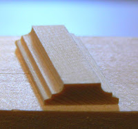
It's based on the same profile used for the bridge and soundboard moldings, except it has two decorative edges instead of one.
Originally I had planned to apply a set of moldings to the inside upper edge of the case, but I discovered, before getting to that point, that Italian harpsichords don't necessarily have an inner molding unless they're made in the false inner-outer style (i.e. a set of veneers are glued to the interior of a painted wooden box to make it look like a separate wood-coloured instrument resides within the box). It's a good thing I didn't go ahead with this, not only because of the workload, but because the resulting cap molding would have been extremely wide. As it is, the molding has to cover and overhang two thicknesses of case material, which requires a width of 3/8" plus 2 mm.
Before gluing the cap molding down, I cleaned up the case edges with a special edge-trimming plane. Since the case edge is so narrow, I thought a normal hand plane would be hard to keep flat. The built-in fence on the edge-trimming plane helps the plane cut a square edge.
I steam-bent the bentside cap molding to get it approximately to the right curvature, then glued it down:

Tiny 1/2" brads were nailed through the molding and partly into the case edge to help resist the shear forces of the molding trying to straighten out. I think I will clip off the heads of these and drive the remainder of the shaft below the surface of the molding, just to provide some extra holding power.
The brads also help to act as positioning pins so that the overhang of the molding is equal on both sides. There's no easy way to keep the molding in the correct position without using positioning aids of some sort.
All the other cap moldings were done the same way, except that the brads were pulled out once the glue dried. Glue alone should be enough to secure moldings that aren't bent to shape.
Next, I'll swell the nail holes with water to close them up as much as possible, sand the molding, and plug any remaining holes with yellow wax.
Sunday, July 19, 2009
Cosmetic details
A little fragment of molding decorates the back edge of each keywell block:

This piece of molding covers the slightly inaccurate joint between the bentside and cheek:

An identical piece covers the bentside-to-tail joint. I found these case joints tricky to make absolutely tight, without gaps: something to improve upon in future. In the meantime, these little sins are now safely hidden.
Keywell blocks
Since the keyboard is narrower than the space it fits into, the remaining space is taken up with a pair of keywell blocks plus a transposing block. The keywell blocks are shown below, glued up against the decorative front edges of the case:

In order to make sure the first and last keys don't rub against these blocks, 2 mm shims were glued to the left and right edges of the key frame:

The removable transposing block, shown below, allows the pitch of the instrument to be changed by shifting the keyboard sideways to fill the space left over when the block is removed. The block is held in place with two rare-earth magnets that are attracted to nail heads inside the keywell.

The keyboard shifts by one jack position, which allows a pitch of A=415 Hz when to the left and A=440 Hz when to the right.
Determining the proper thickness of the keywell blocks is an important part of making sure that the keyboard is properly aligned with the jacks: if not, the jacks could slip sideways off the key ends. I did this by progressively planing the blocks down and putting them in place, then sliding the keyboard left and right and observing how the jacks sat on the keys in both the left and right positions. When everything looked good, I glued the blocks in, then planed down the transposing block to fit the leftover space.

In order to make sure the first and last keys don't rub against these blocks, 2 mm shims were glued to the left and right edges of the key frame:
The removable transposing block, shown below, allows the pitch of the instrument to be changed by shifting the keyboard sideways to fill the space left over when the block is removed. The block is held in place with two rare-earth magnets that are attracted to nail heads inside the keywell.
The keyboard shifts by one jack position, which allows a pitch of A=415 Hz when to the left and A=440 Hz when to the right.
Determining the proper thickness of the keywell blocks is an important part of making sure that the keyboard is properly aligned with the jacks: if not, the jacks could slip sideways off the key ends. I did this by progressively planing the blocks down and putting them in place, then sliding the keyboard left and right and observing how the jacks sat on the keys in both the left and right positions. When everything looked good, I glued the blocks in, then planed down the transposing block to fit the leftover space.
Sunday, July 12, 2009
Register controls
The on/off positions of the registers are controlled by capstan screws at the left and right sides of the harpsichord. Here is the set located at the cheek:

The thickness of the brown block is the same as that of the jackrail supports, which ensures the screw heads won't be blocked by the supports.
By inserting a thin rod into the holes, the screws can be turned in and out. The register ends butt up against them, controlling their sideways motion.
To locate these screws I had to cut down the registers, which were still a bit too long, and this meant I had to have a fair idea of where the on and off positions would be. I determined this by progressively trimming the register ends and trying my prototype jacks in various slots after each cut.
Shifting the registers on and off is controlled by this pair of register levers on the spine side of the instrument:

The handles are brass lamp finials, used to screw down lampshades in a decorative manner. They fit into two brass bars, which I drilled for the necessary screw sizes and polished. At the far end, the registers were drilled for #8-32 machine screws which self-tapped their holes as they were screwed in.
Since the jacks will face in opposite directions, the on and off motions for the registers are opposed. Moving both levers in the same direction silences one stop and turns on the other, while pinching the levers together turns both on.
Thursday, July 9, 2009
Jackrail
The jackrail sits over the register gap and keeps the jacks from flying out of the instrument when the keys are pressed. Its ends slide into grooves milled in the jackrail support blocks.
I made the jackrail from a scrap piece of the quartered western red cedar used for the baseboard, and glued pieces of Alaska yellow cedar to the three visible sides. Then I routed a decorative molding along the top edges, using the same bit that provided the profiles for the soundboard moldings and bridge:

The jackrail is 3/8" thick. The ends were reduced to 1/4" to fit the jackrail support grooves.
On the underside I'll staple one or two layers of 1.5 mm felt cloth to stop the upward travel of the jacks. The cloth doesn't need to absorb the full force of playing the keyboard because the head stop under the keys takes some of that impact too. What's needed is for the jackrail to arrest any further travel of the jacks once the keys have stopped moving. This avoids the unpleasant feeling of the jacks hopping upwards, bouncing off the jackrail and landing back on the key ends, which results in an odd jiggling sensation under the fingers.
Friday, July 3, 2009
Jackrail supports
The jackrail keeps the jacks from flying out of the instrument when it's played. Two supports glued to the case walls above the register gap hold it at the correct position.
Here's one of the two jackrail supports:

Both supports are made from Alaska yellow cedar about 11 mm thick. A 1/4" groove in each will receive the ends of the jackrail. I plan to cut off the non-scrolled end at a 45 degree angle, which will look nicer.
Monday, June 29, 2009
Damper kerfs
The jacks need a slot for the felt damper that mutes the string. This is a simple matter to take care of at the bandsaw:

A stop block controls the length of the kerf, which reaches just below the position of the plectrum mortise. Instead of centring the kerf I positioned it closer to the edge of the jack. This keeps the jack body from bending inwards into the tongue slot when the damper is inserted: instead, it will bend outwards slightly.
The kerf must be tight enough to hold the damper securely; otherwise the damper will work loose over time as it thumps down onto the string.
I tested the inexpensive 1/4" bandsaw blade I had and found its kerf was too wide to provide a good grip. So I used a little trick I read about to reduce the set of the blade teeth: I ran the saw while pressing lightly on the teeth from both sides with a pair of grindstones. After making lots of sparks and several test cuts, I succeeded in getting a kerf of about 0.85 mm, down from the original 1.37 mm. This is tight enough to hold the damper without shifting.
Here is the first prototype jack to be complete in all respects (tongue, axle, spring, end screw, damper and plectrum):

Note that the top of the slot was eased with a triangular file to help insert the damper more easily.
Now it's just a question of completing the jacks by tapping the bottom holes and installing the end screws. I won't cut any more dampers at this time because the damper lengths depend on having all the plectra installed and voiced first, so that the register on and off positions can be properly determined. Voicing must wait until the project is basically done: it's the last thing to do before playing and enjoying the finished instrument.
I am indebted to the renowned organologist and harpsichord maker Grant O'Brien for publishing, on his web site, a detailed description of the construction of several Neapolitan harpsichords, including drawings and photos of his jacks, which I have shamelessly borrowed from. I adjusted his jack dimensions to suit the cutters and router bits I could easily get, but my final product is not significantly different from his except in the choice of wood and my decision to use only one damper, instead of a pair.
Sunday, June 28, 2009
Assembling the jacks
So far, I've assembled a couple of prototype jacks in testing out the jack design. Now that the process is being done for real with actual jacks, here's the procedure.
First, any burrs in the jack body caused by drilling the axle hole are trimmed with a small chisel:

Next, the axle hole in the tongue is enlarged with a miniature reamer:

The looseness of the reamed hole is checked with an axle pin held in a pin vise. The tongue should hang down freely under its own weight:

The jack is temporarily assembled to check the fit of the tongue within its slot:

If necessary, the tongue is sanded a little to narrow it for a looser fit:

Once again, the tongue should hang down freely under its own weight:

3 mm strips are cut from a sheet of 0.005" brass shim stock to make leaf springs:

Individual 19 mm long springs are cut from the strip and slid into the spring slot:

The 3 mm width was chosen to make the spring fit snugly within the slot.
Each spring is pre-tensioned by bending it forward:

Finally, the jack is reassembled:


Each assembled jack is tested to make sure the spring returns the tongue fully to the forward position. At present the springs are stronger than necessary, but they can be adjusted later by bending them back slightly.
Friday, June 26, 2009
Jacks update
Another hiatus from the project just wrapped up and I'm back at work. I ended up modifying my jack design slightly, as I was not able to control the backwards pivoting of the tongue to my satisfaction on the prototypes I made to date. In the bass, the tongue would bounce off the string behind it as the jack descended, due to the large amplitude of the vibrating string.
I now have the tongue flush with the front of the jack, instead of set into the middle of the jack's thickness. With this configuration, the base of the tongue tilts outward and touches the side of the register slot in front of the jack. This stops the tongue from moving too far back. All the other properties of the jack have been preserved, so I'm satisfied.
As of today, I have drilled the axle holes through all the jacks and tongues and routed the grooves for the springs. I'll continue with reaming the tongue holes and cutting brass shim stock for the springs.
Monday, June 15, 2009
Drilling for the axle
The tongue is held in its place within the jack slot by a little axle, which acts as the pivot point for the tongue.
Here's the setup for drilling the axle hole:

The axle hole is made by a #61 drill bit. A tongue is placed within the jack slot, then both are laid face-down on the board and slid to the right until the tongue touches the little nail shaft. At that moment the tongue has also bottomed out in the jack slot. To make sure the tongue is centred within the thickness of the jack, a few slips of index card fit inside the jack slot and shim the tongue upwards. Then the jack and tongue are drilled simultaneously all the way through.
Next, the tongue is removed and its hole is enlarged with a little reamer to enlarge it slightly. This ensures the tongue pivots freely on the axle.
Italian jacks often use a flat brass spring to push the tongue forward once the plectrum slips under the string. The bottom end of this spring rests in a slot of some kind. On some jacks I've seen, a groove was cut in the back of the jack and a slightly thinner piece of wood glued in, leaving behind a little slit. I thought a simpler approach would be to use a diamond burr to route a tiny dovetail slot down through the jack slot for a distance of about 10 mm. Since the slot is narrower in front, the spring can't fall out. A piece of 0.005" brass shim stock is cut to fit this slot, and is made long enough to come up to just below the plectrum mortise. The discrepancy between the bevel angles of the tongue base and the bottom of the slot in the jack gives a little extra clearance to the spring as it comes up behind the tongue from the dovetail slot.
Finally, the tongue is replaced in the jack slot and a 1.0 mm nickel-plated axle pin is pushed through the jack and tongue. The pin is a little shorter than the jack width so there is no excess to trim when it's pushed home.
The business end of a test jack, using a scrap tongue that is punched and holds a plectrum:

Finding the correct position of the axle is critically important. A low axle lets the tongue tilt back quite easily: too far back, in many cases. Then the tongue bounces off the string behind it, creating unwanted noise. There is also the problem of a low axle allowing the tongue to kick backwards just as the plectrum plucks the string. This represents wasted energy that should have gone into the string. In such a scenario, the exact moment the string is released is governed—wrongly—by the jack design, not by the characteristics of the string and plectrum. Worst of all is the lack of fast repetition of notes when the jack has an excessively low axle position.
A higher axle is the way to go, even though it makes the tongue less willing to tilt back. In this case, the spring must be carefully adjusted by experimenting with the spring strength and the position at which it contacts the back of the tongue.
I put together a few trial jack tongues and bodies and drilled the axle in several locations, starting with a position twice as far down as the plectrum mortise (19 mm, in other words). Then I put each trial jack into the harpsichord, installed a plectrum and played notes in various parts of the compass, observing the tongue behaviour. After moving the axle up slightly with each new attempt, I found a position at which the tongue kickback stopped. I also found I had to drill the axle closer to the front face of the jack:

Sunday, June 14, 2009
Punching the mortises
Each tongue has a little mortise which holds the plectrum that plucks the string. This mortise is made by punching a slot through the tongue from back to front.
The punching setup at the drill press is a reasonably simple affair:

Using the drill press gives me a handle to press the punch down with, and also maintains a consistent punching angle. Jacks tend to work better if the plectra angle upwards slightly, so I tilted the table 5 degrees.
The punch itself is a 2.0 × 0.4 mm micro-screwdriver blade held in a small drill chuck. The tip passes through the slot in the maple block, which acts as a hold-down for the tongue and helps to pry the punch off as it is withdrawn. Underneath the tongue a slice of end-grain maple acts as a firm surface to work on. I set up the jig to punch the slot 9.5 mm from the top of the tongue, exactly at the point where the tongues were previously grooved across the back.
Before and after pictures showing how the tongue is punched:


This setup worked quite well in punching the mortises. The trick is to make sure the punch is not significantly wedge-shaped in profile, or it will split the tongue. I'm pleased to say that not a single tongue out of more than 130 was lost this way.
The one minor flaw I discovered is that the punching operation produces a bubble of compressed wood on the front face of the tongue that I had to slice off with a chisel to reopen the mortise. My end-grain maple wasn't a hard enough surface to prevent this from happening. Perhaps it would have been better to use a piece of metal with a small slot in it to allow the screwdriver tip to pass right through the front of the tongue. Otherwise, this was a creditable first attempt.
Friday, June 5, 2009
Jack tongues
The tongue fits in the slot routed into the jack body and is kept in place by a small axle pin. A mortise is punched completely through to receive the plectrum.
Holly, a fine-grained wood, was historically one of the commonly used materials for the tongues. I'm sticking with tradition and will be using the sheet of holly seen in the photo that also shows the resawed walnut the jack bodies came from.
First I cross-cut strips 28 mm wide from the sheet. Each strip can be imagined as a bunch of tongues attached together side-by-side, hence the need to cut across the grain. My tongue slot is 30 mm, but I feel the tongues should stop slightly short of the top of the slot so that the tongue doesn't absorb any of the repeated impacts of the jack hitting the jackrail over and over. That might bend the axle or break the tongue. The tongues will be slightly inset from the front face of the jack, instead of being flush.
Once the strips were made, I chamfered one edge at 25 degrees with a chamfering router bit. This edge will rest against the angled bottom of the tongue slot; the difference in angles between the two (25 degrees versus about 40 degrees) gives me some clearance that will be explained shortly.
Next, I needed to mark where the plectrum mortise would be. On some historical jacks, a small groove across the back of the tongue shows the location, and also thins the tongue to facilitate punching the mortise successfully.
I'm placing my mortise 9.5 mm from the top. That location was marked by making a 1/32" groove with a special small router bit. The groove is about 1 mm deep, reducing the thickness that needs to be punched through from 3 mm to 2 mm:

Individual tongues were sawn from these strips at the bandsaw. With a few strokes of sandpaper, the sawn edges were cleaned up.
A finished tongue:

I punched a test mortise on this one, and luckily it worked without splitting. More on making the mortises in the next post.
Holly, a fine-grained wood, was historically one of the commonly used materials for the tongues. I'm sticking with tradition and will be using the sheet of holly seen in the photo that also shows the resawed walnut the jack bodies came from.
First I cross-cut strips 28 mm wide from the sheet. Each strip can be imagined as a bunch of tongues attached together side-by-side, hence the need to cut across the grain. My tongue slot is 30 mm, but I feel the tongues should stop slightly short of the top of the slot so that the tongue doesn't absorb any of the repeated impacts of the jack hitting the jackrail over and over. That might bend the axle or break the tongue. The tongues will be slightly inset from the front face of the jack, instead of being flush.
Once the strips were made, I chamfered one edge at 25 degrees with a chamfering router bit. This edge will rest against the angled bottom of the tongue slot; the difference in angles between the two (25 degrees versus about 40 degrees) gives me some clearance that will be explained shortly.
Next, I needed to mark where the plectrum mortise would be. On some historical jacks, a small groove across the back of the tongue shows the location, and also thins the tongue to facilitate punching the mortise successfully.
I'm placing my mortise 9.5 mm from the top. That location was marked by making a 1/32" groove with a special small router bit. The groove is about 1 mm deep, reducing the thickness that needs to be punched through from 3 mm to 2 mm:
Individual tongues were sawn from these strips at the bandsaw. With a few strokes of sandpaper, the sawn edges were cleaned up.
A finished tongue:

I punched a test mortise on this one, and luckily it worked without splitting. More on making the mortises in the next post.
Tuesday, June 2, 2009
Jack bodies, part 2
Once all the jacks were planed to the correct thickness, I took them over to the strip sander and sanded the top and bottom ends clean, shortening each jack at the same time to a final length of 9.7 mm.
Next, I measured the thickness of the top and bottom ends. The process of hand-planing something small and short tends to pull the object up into the blade slightly, creating a microscopic taper. I found that most jacks differed by approximately 0.03-0.04 mm from top to bottom. I marked the narrower end with a black marker dot: this end now becomes the bottom of the jack, since it's marginally easier to slip it into the register slot.
Because I plan to use end screws to provide a little adjustability in the jack heights, I drilled pilot holes for 1/2" long #2-56 steel screws in the jack bottoms. This was done using a horizontal boring setup and a wooden rail to keep the jack parallel to the #54 drill bit:

Before the screws go in (once the jacks are completely finished), I'll tap the upper portion of the hole to help the screw get started, but I won't tap it all the way. This means the screw will tap part of the hole itself, which will keep it tight enough that it won't unscrew as the instrument is played.
After drilling, I chamfered all four edges on the bottom of each jack at the strip sander. This makes it still easier to slip the jacks into their register slots.
Now it's time to cut a slot for the jack tongue. The slot goes all the way through the thickness of the jack and terminates with an angled bottom so that the tongue's angled base can stop against it. This will allow the tongue to tilt backward, but will prevent it from tilting forward past the vertical.
Harpsichord makers usually use some type of circular saw blade to make this slot. I'm using a 3-wing slot cutter in a horizontal router table setup to cut a slot 3/16" wide:

To keep the jack from getting chipped, I made a zero-clearance table surface and plunged the cutter up through it. This supports the face grain of the jack and minimizes tearout at the end of the cut:

The walnut strip is a stop block that establishes the 30 mm length of the slot.
Before plunging the cutter through the table, I had to decide exactly where to locate the slot within the width of the jack. Each jack is 13.4 mm wide and the slot is about 4.8 mm (3/16"). I needed to leave room for the damper that will mute the string as the jack settles back down. The damper will slide into a thin kerf parallel to the tongue slot, which means the tongue slot should be a bit off-centre to leave room for this kerf. The simplest thing to do, I decided, was to subtract the tongue slot width from the jack width and divide the remaining width in thirds, with 2/3 assigned to the damper kerf position and 1/3 left over. These jacks will have the damper on the left, so a width of 5.8 mm is reserved for that. Next is the tongue slot at 4.8 mm, and 2.9 mm remains on the right.
The angled base of the tongue slot is made by setting the cutter height to terminate the cut at an angle of about 45 degrees from the jack face. As you can imagine, the higher the cutter goes, the more the cut angle approaches 90 degrees, so it has to be set relatively low. The angle is produced on the underside of the jack, as this photo makes clear:

Once everything was up and running, I found it necessary to use a push block to press the jacks firmly against the table. This minimized the vibration and chattering that the jacks had experienced when fed freehand into the cutter:

The finished slot:

Saturday, May 30, 2009
Jack bodies, part 1
Now for a very critical part of the instrument: the jacks.
Last autumn I resawed some walnut I bought back on my very first lumber buying expedition in August 2007. The walnut was planed to a 4.9 mm thickness, with a projected final jack thickness of about 4.6 mm. After resawing and planing, I stickered everything in layers, under bricks to keep it all flat:

The top item is a sheet of holly 3 mm thick, from which the jack tongues will be made. The sheets of walnut are underneath.
Having sat around for about a year, all this material is quite stable, which is an essential basis for producing jacks that are to be well-behaved.
The first order of business was to slice the walnut sheets up into long strips slightly wider than the finished jacks:

These were stacked together on edge, a dozen at a time, taped together on the underside, and planed to establish the final width of the jacks (13.4 mm):

The jack slots in the register are a bit over 14 mm wide, so there is a clearance of about 0.6 mm. This is fine; in fact it could be a little more and still be OK: Skowroneck's book suggests that even 1 mm of clearance isn't problematic.
These bundles, still taped together, were cut down into individual jack lengths on the bandsaw. I'm aiming for a final length of 9.7 cm, so I cut to 9.8 cm to give me a little room to sand the ends and eliminate the roughness left by the bandsaw. The required jack length is actually 10.4 cm: the extra length will be provided by an end screw that will allow the jack height to be adjusted. I know that historical harpsichords didn't have this little convenience; it's the one place where I feel a modern screw could possibly be useful. A generation ago, horrible modern jacks were made that had far too many screws all over the place: see this web page for photos.
Here's a box full of jack blanks:

The most critical part of the jack body is its thickness; the clearance in this dimension is about 0.2 mm at most. Too little and the jacks might rub in the register slots during the dry winter months; too much and the plucking of the strings will be inconsistent as the jacks wobble around.
I suppose one could thickness jacks by machine until the required dimension is reached, as I did with the edges. However, a machine-planed surface isn't completely smooth; under raking light a washboard-like series of ripples can easily be seen. It's best to hand-plane the jack faces, since the hand plane gives a completely smooth surface without ripples. An alternative might be to thickness-sand instead, but sanding tears wood fibres and mats them down instead of cutting them cleanly like the plane does, and these fibres might decide to stand up again sometime later, compromising the smooth surface. Since the jacks have a more generous clearance in the direction of their width, I don't think there will be any trouble leaving the edges machine-planed. They feel smooth, even if they aren't on a microscopic level.
Here's the setup for hand-planing jacks to a controlled final thickness:

Two hardwood rails are screwed to a plywood board. Each rail has a groove with its base exactly 5.0 mm above the plywood. The hand plane seen at left slides in these grooves. A jack is held in place between the rails as shown below:

Scrap wood pieces keep the jack from shifting sideways or backward as the plane rides over it. These scraps must obviously be thinner than the finished jack so as not to interfere with the plane. Note the white paper shims inserted under the jack: these are used to raise the blank up each time the plane cuts away the top surface.
The hand plane is a Veritas low-angle smooth plane with a 38-degree bevel-up blade. The blade is bedded at 12 degrees, yielding a cutting angle of 50 degrees (York pitch, for the plane experts out there). This yields a smoother surface than the usual 45 degree cutting angle, at the expense of more physical effort to push the plane.
A well-adjusted plane should be able to take off a shaving just one thousandth of an inch thick:

To thickness a jack with this setup, a jack blank is put in place and is planed until no more shavings come off. Then a paper shim 0.07 mm thick is put underneath and the jack is planed again. Next, the jack is turned end-over-end to keep the grain angle at the surface consistent, and the other face is planed and shimmed a few times until the correct thickness is reached:

The final jack thickness is about 4.6 mm. The register slots are about 4.76 mm, and the wiggle of the planed jacks within the registers seems right to me: there's just a little bit of play.
Two registers full of jacks:

The first order of business was to slice the walnut sheets up into long strips slightly wider than the finished jacks:

These were stacked together on edge, a dozen at a time, taped together on the underside, and planed to establish the final width of the jacks (13.4 mm):

The jack slots in the register are a bit over 14 mm wide, so there is a clearance of about 0.6 mm. This is fine; in fact it could be a little more and still be OK: Skowroneck's book suggests that even 1 mm of clearance isn't problematic.
These bundles, still taped together, were cut down into individual jack lengths on the bandsaw. I'm aiming for a final length of 9.7 cm, so I cut to 9.8 cm to give me a little room to sand the ends and eliminate the roughness left by the bandsaw. The required jack length is actually 10.4 cm: the extra length will be provided by an end screw that will allow the jack height to be adjusted. I know that historical harpsichords didn't have this little convenience; it's the one place where I feel a modern screw could possibly be useful. A generation ago, horrible modern jacks were made that had far too many screws all over the place: see this web page for photos.
Here's a box full of jack blanks:
The most critical part of the jack body is its thickness; the clearance in this dimension is about 0.2 mm at most. Too little and the jacks might rub in the register slots during the dry winter months; too much and the plucking of the strings will be inconsistent as the jacks wobble around.
I suppose one could thickness jacks by machine until the required dimension is reached, as I did with the edges. However, a machine-planed surface isn't completely smooth; under raking light a washboard-like series of ripples can easily be seen. It's best to hand-plane the jack faces, since the hand plane gives a completely smooth surface without ripples. An alternative might be to thickness-sand instead, but sanding tears wood fibres and mats them down instead of cutting them cleanly like the plane does, and these fibres might decide to stand up again sometime later, compromising the smooth surface. Since the jacks have a more generous clearance in the direction of their width, I don't think there will be any trouble leaving the edges machine-planed. They feel smooth, even if they aren't on a microscopic level.
Here's the setup for hand-planing jacks to a controlled final thickness:

Two hardwood rails are screwed to a plywood board. Each rail has a groove with its base exactly 5.0 mm above the plywood. The hand plane seen at left slides in these grooves. A jack is held in place between the rails as shown below:

Scrap wood pieces keep the jack from shifting sideways or backward as the plane rides over it. These scraps must obviously be thinner than the finished jack so as not to interfere with the plane. Note the white paper shims inserted under the jack: these are used to raise the blank up each time the plane cuts away the top surface.
The hand plane is a Veritas low-angle smooth plane with a 38-degree bevel-up blade. The blade is bedded at 12 degrees, yielding a cutting angle of 50 degrees (York pitch, for the plane experts out there). This yields a smoother surface than the usual 45 degree cutting angle, at the expense of more physical effort to push the plane.
A well-adjusted plane should be able to take off a shaving just one thousandth of an inch thick:

To thickness a jack with this setup, a jack blank is put in place and is planed until no more shavings come off. Then a paper shim 0.07 mm thick is put underneath and the jack is planed again. Next, the jack is turned end-over-end to keep the grain angle at the surface consistent, and the other face is planed and shimmed a few times until the correct thickness is reached:

The final jack thickness is about 4.6 mm. The register slots are about 4.76 mm, and the wiggle of the planed jacks within the registers seems right to me: there's just a little bit of play.
Two registers full of jacks:

Subscribe to:
Posts (Atom)
