Sunday, September 23, 2007

Laying out the bentside

At this point in time, the baseboard has three final edges: left, front and right. The curvature of the bentside and the tail angle remain to be determined.

Instruments built in the Italian tradition arrived at the proper bentside curvature by simply drawing a curve parallel to the soundboard bridge at a constant distance to the right. So determining the layout of the bentside is equivalent to deciding the bridge curvature, except that the bridge curvature must be highly accurate, while minor variances in the bentside are probably fine as long as everything looks good.

The bridge curvature is not too difficult to determine, as the string lengths through a large part of the compass are based on what is termed Pythagorean scaling. In a nutshell, this means that a string one octave lower than a given string is exactly twice as long, while a string an octave higher is half as long. This might sound quite obvious were it not for the fact that stringed instruments can be made without following this rule exactly. If you wanted to use a lower string less than twice as long, you could choose thicker wire to compensate. Likewise, if a higher string were more than twice as long, additional tension would bring it to the proper pitch.

Other string lengths within the octave are determined using simple whole-number ratios derived from the overtone series. Some examples:


a major 2nd = 8:7
a minor 3rd = 6:5
a major 3rd = 5:4
a perfect 4th = 4:3
a diminished 5th = 7:5
a perfect 5th = 3:2
a major sixth = 5:3
a minor 7th = 7:4
a perfect octave = 2:1 (obviously)


With these ratios, it is in fact possible to specify the length of just one string, fill in the remainder of the octave as above, then start doubling and halving string lengths from there. The one string so specified is called the scale and is usually c above middle c (c'', in Helmholtz notation). The original Trasuntino has a scale of c''=276 mm, which my friendly harpsichord maker advised me to shorten slightly to c''=273 mm. This provides a safety margin in case of major swings in humidity, as well as some protection against "ham-fisted tuning", as he put it (I'm pretty sure he wasn't talking about me). A marginally shorter scale means the instrument doesn't need to be pulled up to quite as high an operating tension as the original, as all the strings are a bit shorter. The home pitch will be A=415 Hz, with the keyboard transposing one semitone to the right.

Instead of the simple ratios above, one can approximate a Pythagorean string scaling fairly well by calculating the string lengths according to an equal-tempered scale. In that case, one multiplies successively by the twelfth root of 2 to find the next lower string, and divides by the twelfth root of 2 to find the next higher string. That's what I've done in making my calculations.

One thing to be aware of is that Pythagorean scaling in Italian instruments usually doesn't determine the entire compass, especially in the bass: if it did, the instrument would have to be quite long to accommodate the bass strings. Often the scaling is Pythagorean from the very top down to c below middle c (c), or, less often, for still another octave (C). The scaling must then alter, in any case, because most instruments have a joint in the bass bridge where it goes off to the left at a sharp angle for the last couple of notes.

My drawing of the Trasuntino has string lengths for all c and f# notes (f# is right in the middle of octave). The scale is pretty close to Pythagorean, but not bang-on. This could be due to the fact that the instrument has been rebuilt several times in the course of its existence. The manner of placing the bridge on the soundboard—it just gets bent to shape by hand and glued down—might introduce minor discrepancies as well. In any case, I calculated a Pythagorean scaling down to c quite easily, then spent the rest of the day thinking about the bass strings and their departure from this pure scale. Eventually I put down some provisional numbers based on the shrinking octave ratios in the bass (it goes to 1.922, 1.712 and so on).

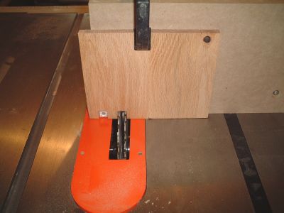
Here is the procedure for laying out the curvature of the bridge on the bottom. First, I clamped one of my registers along the pencil line showing the back of the wrestplank:


This line is at an 8 degree angle and of course the register slot spacing is correct only when tilted to this angle. I put the register on edge because the bottom of each slot provides a convenient edge for my pencil to make a tick mark.

I didn't just lay the register down anywhere along this line. In looking at the drawing, I saw that the leftmost string was 30 mm from the left edge of the instrument. I decided to put my first string at 35 mm, because I'm making my instrument a bit wider. Before committing to this, I located where the first and last strings would be with respect to the leftmost and rightmost slots (about 5 or 6 mm to the side, roughly), to make sure they didn't get placed inconveniently. When everything looked good, I put a pencil tick at 35 mm and aligned the left edge of the first register slot with it before clamping.

After that, it was simply a matter of counting along the slots and putting tick marks on each c and f#. This took only a minute:


Next, I laid my home-made T-square along the baseboard and aligned the left edge with each tick mark in turn. Using a tape measure, I measured out the lengths of the c and f# strings I had already calculated and put a second tick mark on the baseboard in line with the first:


The T-square has a small nail that lines up with the nut location to hold the tape measure. This nail position is fixed because the Trasuntino's nut is straight and perpendicular to the left side. In any other instrument, the nail would have to be repositioned every time the T-square was moved.

Once all the measurements were made, I drove a 1.5" finishing nail into each second tick mark location. Then I bent a long strip of door stop composite (some sort of plastic; very cheap and a nice balance between stiff and flexible) along the nails and held it in place with spring clamps:


And that is how the bridge curvature looks. The actual bentside will be about 4" away from this. I set my dividers to 4" and got a sense of what this might look like by lightly running the dividers along the strip without making a mark. When the time comes to mark for real, I'll run a small engineer's square along the strip and place a compass set to 4" along the edge. This will accurately transfer the curve.

I should point out that the bridge position in the extreme bass is not accurately shown by the plastic strip. The furthest nail is properly placed, but the bridge does not run in a straight line to it. Instead, slightly behind the second-last clamp, the bridge keeps curving to the right and then hooks left to meet the nail.

The tail position is straightforward: at the point where the actual bentside width shrinks to 185 mm (the same width as the bass end of the wrestplank, which is unlikely to be a coincidence), the bentside ends and the tail goes off to the left at a 40-degree angle.

Thursday, September 20, 2007

Knees, liners and layout

At this point in time, I've permanently attached my breadboard edge in place along the front of the baseboard (with a few brads only—no glue!) and cut the right-hand side to a final width of 770 mm: the same width as the wrestplank.

I've marked the locations of the components making up the horse on the baseboard so I can see where they sit even when they're not in place:


The first pencil line you see obviously locates the front edges of the wrestplank support blocks, while the line behind it shows the position of the nut, a strip of wood that will be glued to the wrestplank which defines the front terminus of the sounding length of the strings. In the Trasuntino, the nut is parallel to the front of the wrestplank, which is unusual. Most nuts are tilted at least a bit: the treble end is usually further from the front than the bass end.

That large T-shaped object is a home-made T-square. It will help me in laying out the curvature of the bentside (the curved side of the instrument) along the baseboard by drawing a number of straight lines from the nut towards the rear. The lines will have same lengths as a selected number of strings in the instrument, and their side-to-side location and spacing will be determined by using my newly-made registers as a measuring stick. This whole process merits its own post, so when I get around to it shortly, I'll go into more detail.

Next, I turned my attention to working on the interior framing of the instrument. This consists of a bunch of knees


which are notched triangular blocks (7" x 5", 3/4" thick) at the perimeter of the baseboard, holding up the liners:


The liners, which are 1.5" wide and 3/4" thick, form a ledge upon which the soundboard will rest, in addition to serving as the interior skeleton of the instrument.

That other notch in the back of the knee is parallel to the liner notch and will make it vastly easier to clamp the liner to the knee when the glueup happens.

Although I haven't yet cut out the curve on the baseboard, I thought it would be illuminating to lay out the horse and all the knees in their approximate locations to see how everything would look:


If you look closely, you can see two more knees behind the lower belly rail, propping it up from the back.

Friday, September 14, 2007

Horse: Component parts

The assembly of the wrestplank, the two supports it sits on and two additional boards forms what is called the horse. I have no idea why; it doesn't look at all like a horse, or like anything else, for that matter.

First, confession time: I must admit to having made a small glitch in my wrestplank supports. At the time I cut them, I forgot that I had planned to make them differently than those in the original. They should in fact look like this:


My original supports lacked the cutout you see above, which accommodates the rabbets in the underside of the wrestplank. These new supports will keep the top of the wrestplank and the front edge of the soundboard at the same level—120 mm from the baseboard—which I forgot to take into account the first time around. The registers will lie just behind the wrestplank and the cutout will keep them level with the soundboard as well.

This wasn't a difficult fix; I obtained a small piece of walnut cheaply and set aside the old supports for jack-making material. So there's no need to throw anything away.

The cutout was sized to include a horizontal piece known as the upper belly rail (1/2" thick poplar, 1.75" wide) which stretches between the two support blocks. This is backed up by a larger board—the lower belly rail—which sits on the baseboard of the instrument between the wrestplank supports and reaches almost up to the top edge of the upper belly rail, pressing against its back face. The lower belly rail is 3/4" thick and about 115 mm high. The faces of the belly rails will be glued together where they touch, and both belly rails will be dowelled into every adjoining piece for strength.

Here is a dry fit of all the items making up the horse. The upper belly rail is easily visible, while the lower one is mostly hidden at this camera angle:


With the upper belly rail in place, the gap between it and the back of the wrestplank is 44 mm. The two registers together come to 40 mm; the extra space is deliberately left over to allow free side-to-side movement of the registers. The instrument may contract slightly when it is strung and under tension, so having the extra space is crucial. If things were made to an exact fit, the registers would get squashed between the belly rail and wrestplank if the instrument were to contract too much.

The registers are temporarily laid in the gap so you can see their proper position:


Ultimately the registers will be fastened together in pairs, one register directly above the other. I plan to make the registers removable through a little window in the left side of the instrument. In some instruments the registers can only be removed by taking off all the strings first, so leaving a little access window like this is helpful in case problems develop in future.

As seen here, the horse is nearly done. The back of the treble support block has been left a bit long and needs to be mitred at the same angle as the corner where the bentside and cheek meet. Both supports need a notch in the back to receive the liners, which form an interior rim upon which the soundboard sits. When glue-up time comes, everything will get plenty of dowels, especially the joint between wrestplank and support blocks.

Thursday, September 13, 2007

The registers

Registers (or guides, according to some) are long strips of wood with a series of parallel slots. These slots hold the jacks that carry the plectra up to the strings. The term register is also used to describe the entire set of jacks and strings that make up a stop in the harpsichord: one speaks of "the 8-foot register", for example.

To make the registers, I first cut 5 strips of walnut to a length of 48" and a width of 20 mm. Next, at the router table, I set up to find the mid-point of the width of the strips, as shown below. I used a pointed centre-finding bit that can fit either a router collet or a drill press, and lined it up with a couple of scribe marks that showed the centre line:


Once the fence was properly positioned, I routed out most of the interior of each strip with a 14 mm router bit. The result was a channel with walls 3 mm thick on each side:


The Trasuntino has two registers (two stops), both playing at the same pitch. The plucking points of each are different, however, and this gives a distinct tone quality to each. Guitarists will be familiar with the concept of tone quality depending on where along the string they choose to pluck or strum. It's the same with the harpsichord: the closer the plucking point is to the player, the more nasal the tone, and the farther, the more "round", for lack of a better word.

A total of 4 strips is required because each register must be paired with a lower guide directly below, otherwise the jacks would tend to tip sideways. I cut one extra strip just to be on the safe side.

The original Trasuntino has 50 notes, and I decided to put one extra pair of strings in at the treble so the top c''' wouldn't be lost when shifting the keyboards to high pitch. So each register and lower guide needs 51 parallel slots. Cutting these slots is actually quite tricky, because the spacing must be very accurate. Any minuscule error in positioning adds up over 51 slots to cause a significant discrepancy. A mistake of just 0.1 mm—barely visible to the naked eye—would lead to a cumulative error of 5 mm (almost 1/4") by the time all the slots were cut.

Spacing is also important because the slots reflect the octave width of the keyboard, which in my instrument will be 6-1/2", slightly less than the 6-5/8" in the original: this is a bit much, I think, as it exceeds the octave span of the modern piano and could be a bit uncomfortable. To be precise, the spacing along the register is actually a whisker more than 6-1/2" because the register is tilted by 8 degrees due to the tapering of the wrestplank. If you know trigonometry, you can figure out how much more: it's about 1.6 mm per octave.

I thought a great deal about what kind of jig would make the slots. One way to do it would be to make something like a box joint jig for use at the table saw (box joints are often used to join together parts of a drawer). Stacked dado cutters are set up on the saw to cut slots of the desired width. The jig is fixed to the mitre gauge and has a peg the same thickness as the slots. One slot is cut, then the slot is fitted over the peg, which has been carefully located so that all subsequent slots will be cut at the correct spacing. The whole thing looks like this:


(The image above is courtesy of Dan at Song of the Great Lakes Woodworking Studio, and is used by permission. Check out Dan's page: he's a very skilled woodworker and banjo maker. Thanks, Dan!)

I'm showing you this approach only to tell you that I decided not to use it. My slots were cut at the router table and I ended up using a jig of my own design. One reason was because I wanted to make jacks about 3/16" thick and just under 14 mm wide, and I was able to obtain a 3/16" router bit without difficulty. The other reason was that it seemed that, with a little trigonometry, I might be able to set up the jig and avoid the lengthy trial-and-error process that these types of jigs inevitably entail.

Here is the jig:


An aluminum fence—a kind of "angle iron" extrusion with an L-shaped cross-section—4 feet long, 3/4" wide on each side and 1/8" thick is clamped to the router table at each end. Two strips of wood clamped to the table touch the fence right beside the router bit and keep it from flexing when the jig is used.

At one end, a 1/4-20 screw run through a threaded insert is used to provide fine adjustment capabilities:


The screw has 20 threads per inch, so it's easy to calculate how much it moves with each full turn or portion thereof. Since the screw is at one end of the fence and the router bit is pretty much exactly in the middle, adjusting the screw mechanism a given amount will result in half of that amount at the bit's location.

The registers are tilted by 8 degrees, so I had to make an angled sled that rides along the aluminum fence:


A strip of oak provides the surface that rides against the aluminum, and a piece of poplar is joined to this at a 98 degree angle. This angle is kept rigid with a brace and an added thick block in behind. The poplar has a step cut in it, the depth of which is a bit more than the thickness of the remaining material in the register blank. This is where the register sits while the slots are routed. For fine adjustment of the exact depth of cut, I stuck on layers of green masking tape.

My 3/16" router bit has a fairly short cutting edge, and it also has a 1/4" shank, so I needed to provide a clearance slot for the bit to pass all the way through the width of the register. Because the shank of the bit has no cutting edge, I couldn't just fire up the router and let the bit cut its own slot into the jig. Instead, I nibbled away a good-sized slot at the bandsaw Next, I found a piece of scrap from which I could cut small sections that would fit in back of the slot and act as sacrificial backer blocks to minimize tearout as the router bit exited the register blank. You can see the slot and the sacrificial piece stuck in it below:


You may be scratching your head about all these details, so let me explain the overall idea. The problem in cutting all the register slots is to very accurately set the gap between the fence and the router bit. I determined that my slot spacing had to be 13.89 mm, in order to match the changed octave spacing I wanted to use. Now, there's no way anyone can measure such a small distance properly in this type of setup: the router bit is round, the cutting edges have to be exactly located, the measurement has to be made along a line exactly perpendicular to the fence, and so on. There's virtually no room for error, and even with vernier calipers I doubt if anyone could do this accurately. So this jig takes advantage of the fact that any particular movement of one end of the fence is effectively halved when measured at the router bit. That means you can make a larger and easier movement at the end of the fence and have a 50% smaller movement at the router bit. The screw adjustment (1 turn gives 1/20", or 1.27 mm) allows even finer control: I can easily make 1/8" of a turn, which moves the end of the fence 0.16 mm, which translates into a movement of just 0.08 mm at the bit.

Enough said! Now for the jig in action.

The process starts with one slot already cut in the register blank. The blank is set in the jig, which is pressed against the fence, and the slot is hooked over the fence with the slot's left edge against it. When the jig is pushed forward along the fence, the next slot will be cut at a controlled location. Then that new slot is hooked over the fence, the third slot is cut, and so on. For the register blank to sit securely in the sled, the slots must be cut at least as high as the distance between the green tape and the top of the aluminum fence. The router bit must be raised as high as the fence (3/4").

Why does one slot already have to be cut? The first slot is a fair distance from the edge of the register and the fence would interfere in trying to cut this slot. So each register blank has to get the first slot cut before the jig is set up. I did this with the mitre gauge tilted to 8 degrees. A backer strip supports the register blank, which is kept from shifting around with a bit of double-sided tape:


A pencil mark shows where the first slot will be cut:


Slotted:


The next picture makes all of the preceding verbiage clear. It shows the jig in action: the sled carrying the register blank is pressed against the fence, the previously cut slot is hooked over the fence and the router bit is ready to cut the next slot.


Note that the fence is actually thinner than the width of the slots, which is unlike the setup used in the box-joint jig discussed earlier. This discrepancy is unimportant because all I needed to do in compensation was to press the edge of the slot firmly against the fence as I pushed the sled forward.

Now I must admit that, despite all the clever thinking that went into my jig, I had to do a surprising amount of trial-and-error slotting on scrap pieces before I finally nailed the spacing I wanted. Initially I used a bit of trigonometry to calculate the position of the far end of the fence, which I located with respect to a straight line drawn along the entire router table through the centre of the bit. This was not as accurate as I hoped it would be, so I used it only as an initial position and dealt with the screw adjustment thereafter. In retrospect I think the fence, being of aluminum, is too flexible and that must have thrown off all the careful adjusting I tried to do. Even clamping those two wooden strips behind the fence didn't help much. In fact, I had to watch how I clamped them in place: I could inadvertently bend the fence simply by pushing the strips up against it. So getting the job done was a lot more frustrating than I expected. But, eventually, I ended up with 4 registers that had a first-to-last slot total spacing of 693 mm. This is only a whisker off from my theoretical target of 694.5 mm, and is within reasonable limits of accuracy.

The end product, needing only a bit of careful sanding to remove fuzz and fibers left from the routing:


Eventually these will be cut to final length—they're much too long right now—and assembled in pairs. In some instruments the lower guides are installed underneath the wrestplank, but I'm going to approximate a box guide construction, in which a single rather thick piece of wood has slots punched through it. I'll take pairs of registers and join them together, with spacer blocks inside the long interior groove to keep the two pieces properly aligned and spaced.

In designing this jig, I had to watch out for a couple of potential traps. First, the fact that the slots are routed with the register upside-down, coupled with the 8 degree tilt of the whole assembly, renders everything non-symmetrical. The 8 degree tilt is such that when the registers are in the instrument, the left end of the register is farther away than the right. But I had to make the sled with an 8 degree tilt the other way, because otherwise when the registers got turned right side up, the slots would not be parallel to the sides of the instrument as they had to be. I had to play with a paper mockup of the register with a dozen slots cut in it just to make sure of this. Secondly, I realized I had to adjust my spacing calculations to account for the diameter of the router bit. The slot spacing is left edge to left edge, whereas my original calculations were from left edge to the centre of the router bit. Luckily I realized this not long after starting to design the jig.

The registers are a critical part of the instrument because they determine the shape of things to come. Using the registers and the known lengths of the strings, the curvature of the bentside of the harpsichord can be determined. When the registers are laid across the panel that will become the keyboard, the spacing of the backs of the keys can be properly marked. The positions of the bridge and nut pins are derived from the registers as well. If there are any minor flaws in the placement of the slots, those flaws can be transferred to these other parts, thereby cancelling out any misalignment.

Sunday, September 2, 2007

Wrestplank: Trimming to size

The jagged back edge of the wrestplank was cut off using a tapering jig at an 8 degree angle, and the right-hand side was cut cleanly, resulting in a width of 770 mm: the first cut I've made to establish a final dimension in this project. This is about 1/2" more than the original, which allows me to add an extra pair of strings in the treble so the highest note (c''') will not be lost when the keyboard is transposed to the right.

Next, I cut a 20 mm rabbet along the underside of both the left and right edges, extending halfway through the thickness of the wrestplank. The rabbets will receive support blocks (basically 10 cm planks stood on edge) that hold the wrestplank up from the bottom, allowing room for the keyboard to slide in. The height of these blocks defines the depth of the interior of the instrument, as the liners must end up at the same level.

Below you can see the underside of the finished wrestplank and the rabbets, one of which is not visible due to the camera angle:


Here is a dry-fit of the left support block in its rabbet:


The joint between the wrestplank and its supports must be very strong. I'll put about a half-dozen 3/8" dowels through the wrestplank from above and sideways through the block to firmly pin this joint together.

Animals?

This afternoon when I stepped into the garage to continue the project, I was unable to locate my earplugs. I had two foam earplugs connected by a plastic cord to keep them from getting separated. When I finally found a trace of them, only the plastic cord remained.

My conclusion is that during the night, some animal got into the garage somehow (it was closed), sniffed the tasty earwax on the earplugs, and simply ate them (!) leaving behind the cord that connected them. The cord ends looked neatly snipped as if by scissors.

Yes, I know it sounds gross, but everything is food for something in this world.