Wednesday, December 26, 2007

Soundboard: Intermediate glue-up stages

I'm still gluing the soundboard together, as my glue has a long clamping time.

After making up 4 pairs of boards, the next step is to glue 2 consecutive pairs together. A full-sized sheet of plywood now acts as the work surface:


Note the second glue-up of short pieces at the back of the work surface, as well as the extra shims needed to keep pressure against the full length of the glue joint: these compensate for the staircase-like profile of each pair of boards.

Before gluing, I spent the morning levelling and cleaning up the glue joint of each pair with a cabinet scraper. The process was tiring, as there is quite a bit of friction in pulling the scraper along the surface, but the tool did a great job of taking off thin little shavings.

Tomorrow, after scraping the product of this intermediate stage, each set of 4 boards will be glued together to complete the soundboard.

Monday, December 24, 2007

Soundboard: Glue-up

Today I completed the process of planing my boards down to about 3.5 mm. After laying the boards edge-to-edge, I chose to rejoint two edges just to clean them up. Then I trimmed a bit from the front of each board, as the planer had sniped each one a bit at the end of each planing pass.

Next I brought out the instrument, which has been resting in a corner of the workroom since the framing was finished in early November, and started laying out the soundboard wood in sequence on top of the liners. I clamped the leftmost board in place along the spine, keeping the closest edge about 1/4" in front of the upper belly rail, and marked the final length of the board about 1" beyond the far end of the liners. Each board received the same treatment, and as each was trimmed it was replaced back onto the instrument in sequence. Here's a picture of the process:


I'll use the off-cuts to make up a cosmetic veneer for the wrestplank surface.

Originally my plan was to make the soundboard long enough that the front portion would be cut off and made into the wrestplank veneer. Unfortunately, several of my boards have defects close to the far end, and if I had pulled them all forward so that they were flush with the front end of the wrestplank, these defects would have ended up on the finished soundboard. I'd rather not have knots and splits on my soundboard. By keeping the front edge of the boards almost flush with the upper belly rail, the defects end up beyond the perimeter of the instrument, where they can safely be cut out.

At last the time came to actually start gluing the boards edge-to-edge. I made up a gluing platform consisting of an 8-foot section of plywood, two 8-foot long pine boards, clamps, wedges and a bunch of bricks.


The bricks got wrapped in paper because they like to shed red dust all over the place.

One pine board was clamped parallel to the long edge of the plywood. A sheet of wax paper was laid down and two soundboard planks were placed on top. A long skinny off-cut of soundboard wood was placed along the edge of the second plank, and the second pine board was clamped about an inch away from this. Numerous pairs of wedges were inserted between the pine board and the off-cut.

The actual glue-up is quite simple. Two soundboard planks are folded together face-to-face to expose the mating edges and a bead of fish glue is squeezed on and brushed out. After replacing these planks on the plywood sheet, the wedges are squeezed together, which presses the two planks together, the off-cut serving to protect the outside edge from being indented by the wedges. Bricks are placed on top to keep everything from buckling upwards as the pressure increases. The set-up looks like this:


The "gift-wrapped" bricks ended up that way because they were still shedding dust.

With this set-up, I can glue up several pairs of boards each day. There are 8 boards in total, and I'll soon be able to glue 2 pairs of boards together, and so on until the entire soundboard is complete.

This method is similar to what harpsichord makers did centuries ago in gluing up their soundboards, according to surviving accounts.

Sunday, December 23, 2007

Soundboard: Edge jointing

Last weekend, after jointing one edge of my soundboard material at the router table, I took each board to the table saw and sawed defects from the edges. This shrank the widths of each board somewhat, but it was necessary to get rid of large knots and pitch pockets, which might have weakened the board and could have been torn out during planing or jointing.

Next I set up the planer and started planing each board face until roughness and oxidized wood vanished. I removed only enough to clean up each face. When this was done the material was from 6-7.5 mm thick, so I continued planing all the boards in sequence on the same planer setting to get their thicknesses to match. Since the material is quite thin, I rode each soundboard piece on top of an 8-foot long pine backer board: this is safer than trying to send something very thin through a planer on its own.

The boards are now about 5 mm thick, and I'm aiming for a starting thickness of 3.5 mm. My friendly harpsichord maker advised a thickness of a "heavy eighth inch", an even eighth being about 3.2 mm.

I jointed the sawn edges of each board to clean them up, and as an experiment I tried laying boards edge-to-edge to see how well they fit. Even after several light jointing passes, the boards wouldn't quite come together. It appeared that the length of the jointer fence was insufficient to remove a very subtle bow from the edges.

I thought I might have to invest in a good-quality large hand plane such as a jack plane, which together with a shooting board is usually what is used for jointing soundboard planks. But, after consultation with my father, we decided to adapt the shooting board principle to the router table and save the expense of the plane, which would easily be over $200.

A traditional shooting board is a long wide board to which a second narrower board is fastened. The step between the boards receives a long hand plane laid on its side, and the material to be jointed is placed atop the narrower board with the edge slightly overhanging it. The plane is pushed forwards and, guided by the edge of the narrower board, planes the edge of the desired board straight. Using a long plane ensures that any minor defects on the narrow board's edge are bridged by the plane's long sole.

We came up with a shooting board made of a 12" wide piece of medium-density fiberboard (MDF). MDF is flat, straight, stable, heavy and cheap. Atop this went a narrower piece of MDF with five slots at right angles to the long edge. Five carriage bolts were inserted through the large piece from below, with the heads countersunk, and hand knobs were screwed onto the opposite ends to hold the narrow piece down.

The slotted narrow piece acts as an adjustable fence. A piece of soundboard wood is laid against it and the fence is adjusted until the soundboard material just slightly overhangs the edge of the bottom board. Then the knobs are tightened to hold the fence in place. The entire package is pushed through the router table with the bottom edge running against a piloted router bit. This shaves the soundboard plank flush with the MDF edge.

In action the shooting board looks like this:


It's "incredibly ugly", as my father put it, but it cost $20 to make and it works. The bricks weigh down the soundboard plank and keep it from shifting around as the assembly is pushed forward.

This router bit


takes care of the trimming. You can see the pilot bearing running against the MDF edge.

After jointing each edge once and trying planks side-by-side, the fit is pretty much perfect.

Saturday, December 15, 2007

Soundboard: Selecting boards

At long last I am ready to begin work on the soundboard.

The wood, as you will recall, was purchased back in October and has been sitting around for about two months. Vogel sent me something like 2 square metres, which is almost twice as much as I need, but the material only comes in increments of 1 square metre. It's good to have some extra in case something goes wrong; perhaps I'll build a smaller instrument someday with the remainder.

I spent several hours recently going through all the wood again, thinking about how to put it to best use. There are a number of considerations to balance in selecting the planks:
  • It would obviously be wasteful to cut a long board into short pieces for use in the treble, especially since Vogel specifically sent me a variety of lengths. So the longest boards should ideally remain in the bass.
  • The boards are sounded out by rapping them with one's knuckle. The idea is that "ringier" boards are better suited for the bass, while duller-sounding ones should go higher up. This is complicated somewhat by the fact that the boards are mostly of different lengths and sound different by virtue of that alone. I gave it my best shot by aiming to have some sort of gradation of "ringiness" as I arranged my boards from left to right.
  • I've heard suggestions that coarser-looking grain should go in the bass and finer grain in the treble. One of my books says that there shouldn't be wild changes in grain density from one board to the next. My boards seem pretty good in this respect, except for one that has a patch of very wide rings right in the middle.
  • My friendly harpsichord maker says that if boards want to bow, they should be arranged so they all bow upwards. The soundboard in a finished harpsichord is slightly crowned anyway, so any natural tendency of this sort should be noted and taken advantage of.
  • Grain runout must be accounted for. Wood fibers don't run perfectly horizontal in sawn lumber but come up to the surface at an angle. On rough lumber, these little whiskers can be stroked with the fingertips: one direction feels rough, while the other is smooth (like a cat's fur). This must be noted when planing, otherwise the blade can catch the whiskers and start ripping fibers out of the surface like a loose thread being pulled on a garment. If the boards are properly oriented, however, the blade simply trims the fibers harmlessly.
After examining my collection of boards with all these factors in mind, I chose the requisite quantity, arranging them suitably from left to right, decided which face might end up as the visible upper surface—though it's a bit early to be completely sure, as the boards are still rough—marked down the grain runout on each face and made a note of defects such as chips and knots. Although the wood is of good quality, most boards have some knots or pitch pockets (near the edges, fortunately) that will have to be cut out. The exception is the left edge of the lowest board, which will be glued to the spine liner, so any modest defects there are unlikely to have an impact on the sound.

Today I did some preliminary straightening of one edge of each board. Since the wood is rough-sawn, all four surfaces will need attention, but everything must start with one straight edge to place against the table saw fence. The two longest boards were not that straight—one of them was out by about half an inch in the middle—so I had to attach a long straight board with double-sided tape to each of these in turn and run the whole package through the router table to get a half-decent straight edge. I was impressed by the gigantic splinters that flew all over the place as I did so: the wood is quarter-sawn, so the router bit was basically splitting the edge off along a growth ring. Still, no damage was done, and at least I can now take all this lumber to the table saw. Here it is, waiting for tomorrow:

Key panel, key frame and miscellaneous details

I've been busy this past month with various concerts, so I've collected smaller bits of work I've done over the past little while into this single post.

Back in October I glued up the key panel, out of which the keyboard will be made. This consists of several 1/2" thick basswood boards 6.5" wide (the width of one octave) and of varying lengths to suit the 8-degree taper that the keyboard must have in order to fit inside the instrument. The key panel isn't a big deal at this early stage, but here's a picture anyway:


It still needs to be cut off straight (but at an 8-degree angle) along the back.

This will sit on the key frame, which is made of soft maple:


The key panel, when cut to size, will be almost flush with the front of the key frame and somewhat short of the back edge. At the back, the rack—that strip of maple sitting behind the key frame—will be glued on edge. This will have a series of vertical slots which will accept a metal pin driven into the end of each key. When the key is depressed, the pin and slot will ensure it moves straight up and and down.

The balance rail—the chamfered rail in the middle of the key frame—will be the pivot point for the keyboard. Each key will have a mortise punched most of the way through it from above, and a pin will pass through this mortise into the balance rail. This second guide point together with the rack will keep the keys moving vertically, without skewing sideways and touching their neighbours.

Back in mid-September, I visited A&M Wood Specialty again and selected a large plank of Alaska yellow cedar to use for the exterior casework of the harpsichord. I ended up with a board about 9 feet long, 10 inches wide and 1" thick (all rough dimensions). Since the moisture level of this board was a bit high, I purchased it and arranged to have A&M keep it for me until it dried out somewhat. By late November the board was ready to go, so I had A&M resaw and surface all the resulting pieces to my required final dimensions of 7.5" wide, 3/16" thick. They did an excellent job for an eminently reasonable fee of about $25. I ended up with 4 long resawn boards plus one thicker full-length piece that came from the original board when it was ripped to width. This will be used for mouldings, of which there are a great many on an Italian instrument.

Alaska cedar is a lovely wood of pale yellow colour and very subtle straight grain: it's quartered so the grain is quite even. It has an oddly herbal smell when freshly-cut, quite unlike the usual resinous evergreen fragrance. In fact it smells as if someone has been smoking pot somewhere nearby!

The case wood is thin, so the bentside can be made by simply shoving a board against the glue-smeared knees and clamping until the glue dries. Other sides are treated similarly, except that they need no bending. The numerous mouldings that go along the top and bottom edges of these boards will also strengthen them and keep them from being too floppy. A nice example—one of many in the Italian harpsichord tradition—of form and function being combined.

During the course of October and November, various items needed for the harpsichord arrived from various destinations: cloth padding of various types, boxwood plates which will make up the natural key covers, strips of ebony from which the sharps will come, maple arcades to decorate the front edge of each key, tuning pins, bridge pins, hitch pins, and so forth. I was lucky to have purchased all this stuff at a time when the Canadian dollar was skyrocketing to all-time highs against the US dollar. It also gained against the Euro, which helped offset the cost of buying things from Europe.

My sources are:

The Instrument Workshop: cloths, key covers and sharps, some specialty tools, plectra and strings.
Hubbard Harpsichords: maple arcades and specialty drill bits.
MicroMark: several small tools.
Marc Vogel oHG: brass and iron pins of all sorts, soundboard rose, soundboard wood.

Friday, November 9, 2007

Interior framing complete

As of today the interior framing of the instrument is complete:


The instrument received some additional reinforcement in two forms. Firstly, several braces were attached along the full width of the bottom. The stress from the strings pulling on the bentside liner, if one thinks about it, is transferred from the notch at the top of the knee down to the base of the knee, and might cause the bottom to buckle somewhat. Four braces made of Douglas fir, which is strong and stiff, help keep the bottom flat to resist this.

Secondly, a couple of "flying buttresses", also out of Douglas fir, were wedged in between the bentside liner and the bottom. These required some rather complicated compound cuts on each end, which my father ended up calculating on paper. Two of these go at the bass end of the bentside, where string tension is high, and one goes in the treble near the cheek, which is a problematic area in many harpsichord designs: the soundboard often cracks in the treble and creeps into the register gap. Since the compound cuts were close but not quite perfect, I secured the buttresses with epoxy, which has reasonable strength across gaps (most glues are strong only when the joinery is tight).

Lastly, the joints between bentside liner and knees were reinforced with #8 wood screws as extra insurance, and dowels secured the far end of the spine and bentside liners to the corner blocks at the tail of the instrument.

I've inscribed a dated note marking the completion of this stage on the back face of the lower belly rail.

Thursday, November 1, 2007

Bentside liner

This merits its own post, even though it is part of the interior framing mentioned in the previous post.

Wood can be bent by soaking, steaming or dry-heating it and then bending it around a curved form. After clamping for a while, it will mostly hold that curve, although it will try to return to its original shape at least a little: a phenomenon known as "springback". Alternatively, one can cut a number of closely spaced saw kerfs along the inside of the curve, and then bend the wood to the desired shape. Although the kerfs weaken the wood, the act of bending closes them up to a fair degree, which restores some strength. In a harpsichord, the kerfs are largely filled up with glue when the bentside and liner are glued together, and this restores even more strength.

I experimented with a poplar scrap the same dimensions as my liners (3/4" thick by 1.5" wide) by clamping it and cutting a series of kerfs spaced 1/2" apart, and cutting through all but about 1/4" of the total thickness. This fine-toothed hand saw proved to have a suitably narrow kerf:


The kerfing parameters were suggested by reading professional harpsichord makers' advice on the harpsichord mailing list. After trying this scrap against the steepest part of the treble curve, I found it would bend readily enough when clamped, even though bending it by hand seemed to imply it wouldn't bend far enough. Obviously it must only be bent inward: the wood breaks all too easily when bent the wrong way, as I found out by deliberately flexing it in the opposite direction (note the broken end above).

This little experiment seemed promising enough, so I cut my actual bentside liner stock a little over-length and got to work. In the treble, I started out conservatively with kerfs 1/2" apart for a small distance, then switched to 1" apart with the idea of going back and filling this portion in with more kerfs later on if necessary. I repeatedly clamped the liner in place as much as I could and tried to bend the unkerfed portion inward carefully. Further down the liner, I switched to kerfs 2" apart, then 4" apart. The kerfs ended up going almost the full length of the liner, though they were of course widely spaced at the far end.

By trial and error—and not as much as I thought I'd need—I went back and filled in some of the treble areas with additional kerfs. I discovered that I'd need to tweak the notch in the treble wrestplank support block to accommodate the curve that the liner wanted to take, so I did that with a 1" chisel. I mitered the far end of the liner at 55 degrees to match the right-hand corner block angle.

Eventually I decided the fit was good. I checked first by eyeballing, then by running a square along the edge of the baseboard and seeing whether the liner curvature was aligned with the curved edge of the baseboard. For the most part the fit was very good. In one place it might be necessary later on to sand the liner a bit; in another, the baseboard edge might need sanding. Before I decide this for sure, I'll clamp my case material in place and see if the boards can conform to these little discrepancies; I suspect they might do so readily enough: the case wood is 3/16" Alaska yellow cedar. The mismatches are very slight, perhaps 1.5 mm or less, so they might not need any correction at all.

On to the glue-up: polyurethane glue again, and C-clamps to bring the liner in against the knees, with more clamps from above to push them into the notch. I took pictures from several angles:


An arrangement of blocks at the bass end of the liner captures the mitered end and keeps it from slipping out of alignment with the tail liner.

Note that I've left the treble end of the liner over-length: it is far easier to leave a generous margin and cut it flush later then to guess the correct length and pre-cut it.

I'm pleased with the way this turned out; it wasn't as difficult or time-consuming as I thought it would be.

After the glue dried, I cut off the overhanging treble portion of the liner and took everything outside to chamfer the inside edges of all the liners. An extended router baseplate helped keep the tool steady:


Where the router couldn't reach—it was blocked by the tip of each knee and in deep corners—I finished the chamfer with a chisel and sandpaper.

Monday, October 29, 2007

Interior framing

With the horse now glued to the baseboard, the interior framing continues with the gluing of the knees. I traced out the places where I wanted them, making sure that they were at right angles to the edge of the baseboard and exactly flush with the edge. Getting a right angle was easy on the spine and tail, and as for the bentside, I basically eyeballed the knee placement there. There are 8 knees on the bentside, spaced a bit closer together in the treble where the curvature is tighter and more widely towards the bass. The spine is supported by three knees, and the tail has one in the middle.

Before gluing the knees, a pair of small holes was drilled through the baseboard to mark the correct location for dowel holes drilled from beneath, as mentioned earlier.

The knees were glued with polyurethane glue. The back corner was fastened with a single brad, while the front was clamped:


Using a pneumatic nailer was very helpful, as I could hold the knee in place and have it instantly nailed down at the back without things shifting around.

Note the two corner blocks at the tail: these will be the endpoints of the spine and bentside liners.

When the glue dried, lots and lots of holes were drilled and dowels fitted: 3/8" dowels to hold the underside of the wrestplank support blocks, and 1/4" dowels to hold the knees, corner blocks and lower belly rail edge.

Next, the spine liner was glued in place:


This is joined to the bass wrestplank support with a pair of dowels and is cut short of the tip of the instrument by the width of the tail liner (seen resting loosely on the opposite corner block). The tail liner will overlap both the spine and bentside liners to keep it from shifting under string tension.

Having prepared the tail liner to its final dimensions, it gets glued on next:


Behind the tail you can see my length of door stop composite lying on the spine liner. It will help me in getting a preliminary idea of the bentside liner's curvature.

Making the bentside liner will be the tricky part: it will be kerfed (i.e. a bunch of saw cuts will be made most of the way through its thickness) to make it flexible, and is likely to require some trial and error to determine how to best do it. I have a spare piece of poplar lying around to practice on before I try this for real.

Friday, October 26, 2007

Horse and baseboard united

Nothing earth-shaking, perhaps, but today the horse was at last glued onto the baseboard:


Before doing so, the joints between the wrestplank support blocks and the lower belly rail were dowelled. Since I intend to dowel into the lower edge of the belly rail and the two knees supporting it, I traced out the position of these components with pencil, and just before gluing, I drilled a series of tiny holes through the baseboard, positioning them at the midpoint of the thickness of the knees and belly rail. When the glue is dry, I'll drill larger dowel holes from beneath, using these little ones as markers, without having to guess where the components are on the other side of the baseboard.

I've also laid out the positions of the knees in pencil, and once again I'll drill small locator holes to help me dowel them after they are glued down.

Thursday, October 25, 2007

Soundboard wood

Now the single most expensive part of the project is at hand: my soundboard wood, which I ordered earlier this month from Germany, finally arrived the other day. I had to go out to the airport, get the paperwork for clearance through Canada Customs myself (no brokers were used, but fortunately the transaction was quick and painless), then take the clearance forms to the shipping company's warehouse, have them release the package to me and get it home in my van. The package was an 8-foot long sandwich of spruce boards between two half-sheets of plywood. It just barely made it into the van.

I told the wood suppliers what I was aiming to make, so they provided boards in various lengths to suit my needs. I stacked and stickered everything to help it dry out, as the boards had been steamed for a while to remove stresses after they were resawn. Here are the two piles in the basement workshop:


This is alpine spruce from Europe. Trees that grow at high altitude have tightly-spaced growth rings because the growing season is short and cold. For use in soundboards, the wood should ideally be quarter-sawn. I received it about 1/4" thick; it will be planed down to about 1/8", glued up and then selectively thinned by hand-planing.

Having such expensive materials to deal with—the total cost, including shipping, duty and taxes must be at least $750 Canadian—makes me a bit nervous. In addition, there is no substitute for prior experience in making a soundboard, which I admit is a liability for me. Thinning down a soundboard is not a mathematical exercise: since no two pieces of wood are alike, the degree of thinning suitable for one soundboard is unlikely to match any other soundboard. You must work your materials in a way that accounts for the idiosyncrasies of what you have at hand, and that will vary from board to board. Still, I have to get my feet wet with this eventually, and I will give it my very best shot.

For now, everything will have to dry out for a while. Cold, dry weather is approaching, and I have the boards stacked up in the furnace room, which is warm and dry, to help things along.

Sunday, October 14, 2007

Horse: Gluing together

Once again, my current professional schedule leaves me with little time to work on the project, but there are some little things I've been able to do that didn't take too long.

I have now glued the component parts of the horse together. First the wrestplank was glued to its two support blocks, using the same polyurethane glue that helped assemble the component parts of the pinblock:


Next, the upper belly rail was glued in place:


Once the glue dried, I drilled holes for dowels to reinforce the joint between the wrestplank and support blocks, and between the upper belly rail and support blocks:


These dowels compensate for the fact that some adjoining surfaces in the horse involve end grain, which does not form the best glue joints. I sized end-grain edges with a thin coat of glue to try to counteract their tendency to suck up glue and thereby deprive the joint of it, but the dowels provide additional security.

I did a little work on the lower belly rail as well, gluing its two knees to the back and nailing them in place while the glue dried:


The silver-coloured metal angles are right-angle assembly guides, which hold the knees square until the glue dries.

Although I had earlier thought about first gluing the lower belly rail to the back of the horse, and then gluing the knees against the lower belly rail, some dry-assembly experiments convinced me that the lower belly rail was too tippy to glue against the upper belly rail and still guarantee a good right angle with the baseboard. That's why I decided to glue the knees to the lower belly rail now, so that it will be held at a right angle once it is glued to the bottom.

Since I need to drill dowel holes to reinforce the joint between the lower belly rail and the support blocks—another end-grain gluing situation—I decided to glue the lower belly rail to the horse now, and make the horse a complete unit that will be attached all at once to the baseboard:


Drilling the dowel holes will be much easier while the horse is still separate from the baseboard. Once the joints are secure, the horse will be glued down at last.

If you look closely, you can see two dowel holes drilled into the right-hand wrestplank support block. These will hold the spine liner in place. I also took the opportunity to chamfer all the inside edges of the horse that will come into contact with the soundboard, just to free its edges a little bit once it is glued down.

Wednesday, October 10, 2007

Baseboard: Cutting out the bentside and tail

I've been busy with various professional commitments since my last post, but I managed to find a few spare moments to work on the baseboard.

In describing how the curvature of the bentside was laid out, I mentioned that the bentside shape had to be corrected at the tip of the instrument. I managed to do so by nudging the far end of my plastic strip (shown in an earlier photo below) about an inch to the right, and then I traced out the final position of the bentside parallel to the strip and 95 mm to the right. I also drew a line parallel to the left side of the instrument at a distance of 185 mm. At the point where my bentside curve encountered this straight line, the bentside ended and a straight line angling leftwards at 40 degrees defined the tail of the harpsichord. Where this line met the left edge of the baseboard denoted the final length of the instrument, which worked out to 2245 mm (about 88.5"), just a whisker off from the original 2242 mm.

Then it was simply a matter of taking the baseboard outside and sawing out the curve with a jigsaw. I smoothed the edge with a file and let my mother, who has a good touch for sanding, clean up the edge even further:


The finished product:

Sunday, September 23, 2007

Laying out the bentside

At this point in time, the baseboard has three final edges: left, front and right. The curvature of the bentside and the tail angle remain to be determined.

Instruments built in the Italian tradition arrived at the proper bentside curvature by simply drawing a curve parallel to the soundboard bridge at a constant distance to the right. So determining the layout of the bentside is equivalent to deciding the bridge curvature, except that the bridge curvature must be highly accurate, while minor variances in the bentside are probably fine as long as everything looks good.

The bridge curvature is not too difficult to determine, as the string lengths through a large part of the compass are based on what is termed Pythagorean scaling. In a nutshell, this means that a string one octave lower than a given string is exactly twice as long, while a string an octave higher is half as long. This might sound quite obvious were it not for the fact that stringed instruments can be made without following this rule exactly. If you wanted to use a lower string less than twice as long, you could choose thicker wire to compensate. Likewise, if a higher string were more than twice as long, additional tension would bring it to the proper pitch.

Other string lengths within the octave are determined using simple whole-number ratios derived from the overtone series. Some examples:


a major 2nd = 8:7
a minor 3rd = 6:5
a major 3rd = 5:4
a perfect 4th = 4:3
a diminished 5th = 7:5
a perfect 5th = 3:2
a major sixth = 5:3
a minor 7th = 7:4
a perfect octave = 2:1 (obviously)


With these ratios, it is in fact possible to specify the length of just one string, fill in the remainder of the octave as above, then start doubling and halving string lengths from there. The one string so specified is called the scale and is usually c above middle c (c'', in Helmholtz notation). The original Trasuntino has a scale of c''=276 mm, which my friendly harpsichord maker advised me to shorten slightly to c''=273 mm. This provides a safety margin in case of major swings in humidity, as well as some protection against "ham-fisted tuning", as he put it (I'm pretty sure he wasn't talking about me). A marginally shorter scale means the instrument doesn't need to be pulled up to quite as high an operating tension as the original, as all the strings are a bit shorter. The home pitch will be A=415 Hz, with the keyboard transposing one semitone to the right.

Instead of the simple ratios above, one can approximate a Pythagorean string scaling fairly well by calculating the string lengths according to an equal-tempered scale. In that case, one multiplies successively by the twelfth root of 2 to find the next lower string, and divides by the twelfth root of 2 to find the next higher string. That's what I've done in making my calculations.

One thing to be aware of is that Pythagorean scaling in Italian instruments usually doesn't determine the entire compass, especially in the bass: if it did, the instrument would have to be quite long to accommodate the bass strings. Often the scaling is Pythagorean from the very top down to c below middle c (c), or, less often, for still another octave (C). The scaling must then alter, in any case, because most instruments have a joint in the bass bridge where it goes off to the left at a sharp angle for the last couple of notes.

My drawing of the Trasuntino has string lengths for all c and f# notes (f# is right in the middle of octave). The scale is pretty close to Pythagorean, but not bang-on. This could be due to the fact that the instrument has been rebuilt several times in the course of its existence. The manner of placing the bridge on the soundboard—it just gets bent to shape by hand and glued down—might introduce minor discrepancies as well. In any case, I calculated a Pythagorean scaling down to c quite easily, then spent the rest of the day thinking about the bass strings and their departure from this pure scale. Eventually I put down some provisional numbers based on the shrinking octave ratios in the bass (it goes to 1.922, 1.712 and so on).

Here is the procedure for laying out the curvature of the bridge on the bottom. First, I clamped one of my registers along the pencil line showing the back of the wrestplank:


This line is at an 8 degree angle and of course the register slot spacing is correct only when tilted to this angle. I put the register on edge because the bottom of each slot provides a convenient edge for my pencil to make a tick mark.

I didn't just lay the register down anywhere along this line. In looking at the drawing, I saw that the leftmost string was 30 mm from the left edge of the instrument. I decided to put my first string at 35 mm, because I'm making my instrument a bit wider. Before committing to this, I located where the first and last strings would be with respect to the leftmost and rightmost slots (about 5 or 6 mm to the side, roughly), to make sure they didn't get placed inconveniently. When everything looked good, I put a pencil tick at 35 mm and aligned the left edge of the first register slot with it before clamping.

After that, it was simply a matter of counting along the slots and putting tick marks on each c and f#. This took only a minute:


Next, I laid my home-made T-square along the baseboard and aligned the left edge with each tick mark in turn. Using a tape measure, I measured out the lengths of the c and f# strings I had already calculated and put a second tick mark on the baseboard in line with the first:


The T-square has a small nail that lines up with the nut location to hold the tape measure. This nail position is fixed because the Trasuntino's nut is straight and perpendicular to the left side. In any other instrument, the nail would have to be repositioned every time the T-square was moved.

Once all the measurements were made, I drove a 1.5" finishing nail into each second tick mark location. Then I bent a long strip of door stop composite (some sort of plastic; very cheap and a nice balance between stiff and flexible) along the nails and held it in place with spring clamps:


And that is how the bridge curvature looks. The actual bentside will be about 4" away from this. I set my dividers to 4" and got a sense of what this might look like by lightly running the dividers along the strip without making a mark. When the time comes to mark for real, I'll run a small engineer's square along the strip and place a compass set to 4" along the edge. This will accurately transfer the curve.

I should point out that the bridge position in the extreme bass is not accurately shown by the plastic strip. The furthest nail is properly placed, but the bridge does not run in a straight line to it. Instead, slightly behind the second-last clamp, the bridge keeps curving to the right and then hooks left to meet the nail.

The tail position is straightforward: at the point where the actual bentside width shrinks to 185 mm (the same width as the bass end of the wrestplank, which is unlikely to be a coincidence), the bentside ends and the tail goes off to the left at a 40-degree angle.

Thursday, September 20, 2007

Knees, liners and layout

At this point in time, I've permanently attached my breadboard edge in place along the front of the baseboard (with a few brads only—no glue!) and cut the right-hand side to a final width of 770 mm: the same width as the wrestplank.

I've marked the locations of the components making up the horse on the baseboard so I can see where they sit even when they're not in place:


The first pencil line you see obviously locates the front edges of the wrestplank support blocks, while the line behind it shows the position of the nut, a strip of wood that will be glued to the wrestplank which defines the front terminus of the sounding length of the strings. In the Trasuntino, the nut is parallel to the front of the wrestplank, which is unusual. Most nuts are tilted at least a bit: the treble end is usually further from the front than the bass end.

That large T-shaped object is a home-made T-square. It will help me in laying out the curvature of the bentside (the curved side of the instrument) along the baseboard by drawing a number of straight lines from the nut towards the rear. The lines will have same lengths as a selected number of strings in the instrument, and their side-to-side location and spacing will be determined by using my newly-made registers as a measuring stick. This whole process merits its own post, so when I get around to it shortly, I'll go into more detail.

Next, I turned my attention to working on the interior framing of the instrument. This consists of a bunch of knees


which are notched triangular blocks (7" x 5", 3/4" thick) at the perimeter of the baseboard, holding up the liners:


The liners, which are 1.5" wide and 3/4" thick, form a ledge upon which the soundboard will rest, in addition to serving as the interior skeleton of the instrument.

That other notch in the back of the knee is parallel to the liner notch and will make it vastly easier to clamp the liner to the knee when the glueup happens.

Although I haven't yet cut out the curve on the baseboard, I thought it would be illuminating to lay out the horse and all the knees in their approximate locations to see how everything would look:


If you look closely, you can see two more knees behind the lower belly rail, propping it up from the back.

Friday, September 14, 2007

Horse: Component parts

The assembly of the wrestplank, the two supports it sits on and two additional boards forms what is called the horse. I have no idea why; it doesn't look at all like a horse, or like anything else, for that matter.

First, confession time: I must admit to having made a small glitch in my wrestplank supports. At the time I cut them, I forgot that I had planned to make them differently than those in the original. They should in fact look like this:


My original supports lacked the cutout you see above, which accommodates the rabbets in the underside of the wrestplank. These new supports will keep the top of the wrestplank and the front edge of the soundboard at the same level—120 mm from the baseboard—which I forgot to take into account the first time around. The registers will lie just behind the wrestplank and the cutout will keep them level with the soundboard as well.

This wasn't a difficult fix; I obtained a small piece of walnut cheaply and set aside the old supports for jack-making material. So there's no need to throw anything away.

The cutout was sized to include a horizontal piece known as the upper belly rail (1/2" thick poplar, 1.75" wide) which stretches between the two support blocks. This is backed up by a larger board—the lower belly rail—which sits on the baseboard of the instrument between the wrestplank supports and reaches almost up to the top edge of the upper belly rail, pressing against its back face. The lower belly rail is 3/4" thick and about 115 mm high. The faces of the belly rails will be glued together where they touch, and both belly rails will be dowelled into every adjoining piece for strength.

Here is a dry fit of all the items making up the horse. The upper belly rail is easily visible, while the lower one is mostly hidden at this camera angle:


With the upper belly rail in place, the gap between it and the back of the wrestplank is 44 mm. The two registers together come to 40 mm; the extra space is deliberately left over to allow free side-to-side movement of the registers. The instrument may contract slightly when it is strung and under tension, so having the extra space is crucial. If things were made to an exact fit, the registers would get squashed between the belly rail and wrestplank if the instrument were to contract too much.

The registers are temporarily laid in the gap so you can see their proper position:


Ultimately the registers will be fastened together in pairs, one register directly above the other. I plan to make the registers removable through a little window in the left side of the instrument. In some instruments the registers can only be removed by taking off all the strings first, so leaving a little access window like this is helpful in case problems develop in future.

As seen here, the horse is nearly done. The back of the treble support block has been left a bit long and needs to be mitred at the same angle as the corner where the bentside and cheek meet. Both supports need a notch in the back to receive the liners, which form an interior rim upon which the soundboard sits. When glue-up time comes, everything will get plenty of dowels, especially the joint between wrestplank and support blocks.

Thursday, September 13, 2007

The registers

Registers (or guides, according to some) are long strips of wood with a series of parallel slots. These slots hold the jacks that carry the plectra up to the strings. The term register is also used to describe the entire set of jacks and strings that make up a stop in the harpsichord: one speaks of "the 8-foot register", for example.

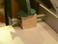
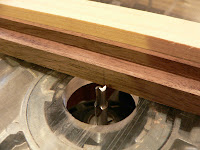
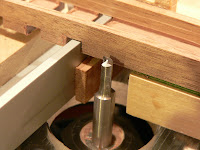
To make the registers, I first cut 5 strips of walnut to a length of 48" and a width of 20 mm. Next, at the router table, I set up to find the mid-point of the width of the strips, as shown below. I used a pointed centre-finding bit that can fit either a router collet or a drill press, and lined it up with a couple of scribe marks that showed the centre line:


Once the fence was properly positioned, I routed out most of the interior of each strip with a 14 mm router bit. The result was a channel with walls 3 mm thick on each side:


The Trasuntino has two registers (two stops), both playing at the same pitch. The plucking points of each are different, however, and this gives a distinct tone quality to each. Guitarists will be familiar with the concept of tone quality depending on where along the string they choose to pluck or strum. It's the same with the harpsichord: the closer the plucking point is to the player, the more nasal the tone, and the farther, the more "round", for lack of a better word.

A total of 4 strips is required because each register must be paired with a lower guide directly below, otherwise the jacks would tend to tip sideways. I cut one extra strip just to be on the safe side.

The original Trasuntino has 50 notes, and I decided to put one extra pair of strings in at the treble so the top c''' wouldn't be lost when shifting the keyboards to high pitch. So each register and lower guide needs 51 parallel slots. Cutting these slots is actually quite tricky, because the spacing must be very accurate. Any minuscule error in positioning adds up over 51 slots to cause a significant discrepancy. A mistake of just 0.1 mm—barely visible to the naked eye—would lead to a cumulative error of 5 mm (almost 1/4") by the time all the slots were cut.

Spacing is also important because the slots reflect the octave width of the keyboard, which in my instrument will be 6-1/2", slightly less than the 6-5/8" in the original: this is a bit much, I think, as it exceeds the octave span of the modern piano and could be a bit uncomfortable. To be precise, the spacing along the register is actually a whisker more than 6-1/2" because the register is tilted by 8 degrees due to the tapering of the wrestplank. If you know trigonometry, you can figure out how much more: it's about 1.6 mm per octave.

I thought a great deal about what kind of jig would make the slots. One way to do it would be to make something like a box joint jig for use at the table saw (box joints are often used to join together parts of a drawer). Stacked dado cutters are set up on the saw to cut slots of the desired width. The jig is fixed to the mitre gauge and has a peg the same thickness as the slots. One slot is cut, then the slot is fitted over the peg, which has been carefully located so that all subsequent slots will be cut at the correct spacing. The whole thing looks like this:


(The image above is courtesy of Dan at Song of the Great Lakes Woodworking Studio, and is used by permission. Check out Dan's page: he's a very skilled woodworker and banjo maker. Thanks, Dan!)

I'm showing you this approach only to tell you that I decided not to use it. My slots were cut at the router table and I ended up using a jig of my own design. One reason was because I wanted to make jacks about 3/16" thick and just under 14 mm wide, and I was able to obtain a 3/16" router bit without difficulty. The other reason was that it seemed that, with a little trigonometry, I might be able to set up the jig and avoid the lengthy trial-and-error process that these types of jigs inevitably entail.

Here is the jig:


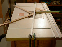
An aluminum fence—a kind of "angle iron" extrusion with an L-shaped cross-section—4 feet long, 3/4" wide on each side and 1/8" thick is clamped to the router table at each end. Two strips of wood clamped to the table touch the fence right beside the router bit and keep it from flexing when the jig is used.

At one end, a 1/4-20 screw run through a threaded insert is used to provide fine adjustment capabilities:


The screw has 20 threads per inch, so it's easy to calculate how much it moves with each full turn or portion thereof. Since the screw is at one end of the fence and the router bit is pretty much exactly in the middle, adjusting the screw mechanism a given amount will result in half of that amount at the bit's location.

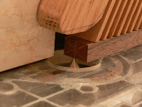
The registers are tilted by 8 degrees, so I had to make an angled sled that rides along the aluminum fence:


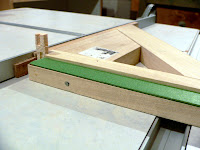
A strip of oak provides the surface that rides against the aluminum, and a piece of poplar is joined to this at a 98 degree angle. This angle is kept rigid with a brace and an added thick block in behind. The poplar has a step cut in it, the depth of which is a bit more than the thickness of the remaining material in the register blank. This is where the register sits while the slots are routed. For fine adjustment of the exact depth of cut, I stuck on layers of green masking tape.

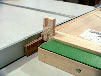
My 3/16" router bit has a fairly short cutting edge, and it also has a 1/4" shank, so I needed to provide a clearance slot for the bit to pass all the way through the width of the register. Because the shank of the bit has no cutting edge, I couldn't just fire up the router and let the bit cut its own slot into the jig. Instead, I nibbled away a good-sized slot at the bandsaw Next, I found a piece of scrap from which I could cut small sections that would fit in back of the slot and act as sacrificial backer blocks to minimize tearout as the router bit exited the register blank. You can see the slot and the sacrificial piece stuck in it below:


You may be scratching your head about all these details, so let me explain the overall idea. The problem in cutting all the register slots is to very accurately set the gap between the fence and the router bit. I determined that my slot spacing had to be 13.89 mm, in order to match the changed octave spacing I wanted to use. Now, there's no way anyone can measure such a small distance properly in this type of setup: the router bit is round, the cutting edges have to be exactly located, the measurement has to be made along a line exactly perpendicular to the fence, and so on. There's virtually no room for error, and even with vernier calipers I doubt if anyone could do this accurately. So this jig takes advantage of the fact that any particular movement of one end of the fence is effectively halved when measured at the router bit. That means you can make a larger and easier movement at the end of the fence and have a 50% smaller movement at the router bit. The screw adjustment (1 turn gives 1/20", or 1.27 mm) allows even finer control: I can easily make 1/8" of a turn, which moves the end of the fence 0.16 mm, which translates into a movement of just 0.08 mm at the bit.

Enough said! Now for the jig in action.

The process starts with one slot already cut in the register blank. The blank is set in the jig, which is pressed against the fence, and the slot is hooked over the fence with the slot's left edge against it. When the jig is pushed forward along the fence, the next slot will be cut at a controlled location. Then that new slot is hooked over the fence, the third slot is cut, and so on. For the register blank to sit securely in the sled, the slots must be cut at least as high as the distance between the green tape and the top of the aluminum fence. The router bit must be raised as high as the fence (3/4").

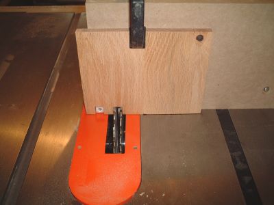
Why does one slot already have to be cut? The first slot is a fair distance from the edge of the register and the fence would interfere in trying to cut this slot. So each register blank has to get the first slot cut before the jig is set up. I did this with the mitre gauge tilted to 8 degrees. A backer strip supports the register blank, which is kept from shifting around with a bit of double-sided tape:


A pencil mark shows where the first slot will be cut:


Slotted:


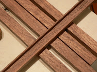
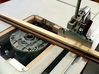
The next picture makes all of the preceding verbiage clear. It shows the jig in action: the sled carrying the register blank is pressed against the fence, the previously cut slot is hooked over the fence and the router bit is ready to cut the next slot.


Note that the fence is actually thinner than the width of the slots, which is unlike the setup used in the box-joint jig discussed earlier. This discrepancy is unimportant because all I needed to do in compensation was to press the edge of the slot firmly against the fence as I pushed the sled forward.

Now I must admit that, despite all the clever thinking that went into my jig, I had to do a surprising amount of trial-and-error slotting on scrap pieces before I finally nailed the spacing I wanted. Initially I used a bit of trigonometry to calculate the position of the far end of the fence, which I located with respect to a straight line drawn along the entire router table through the centre of the bit. This was not as accurate as I hoped it would be, so I used it only as an initial position and dealt with the screw adjustment thereafter. In retrospect I think the fence, being of aluminum, is too flexible and that must have thrown off all the careful adjusting I tried to do. Even clamping those two wooden strips behind the fence didn't help much. In fact, I had to watch how I clamped them in place: I could inadvertently bend the fence simply by pushing the strips up against it. So getting the job done was a lot more frustrating than I expected. But, eventually, I ended up with 4 registers that had a first-to-last slot total spacing of 693 mm. This is only a whisker off from my theoretical target of 694.5 mm, and is within reasonable limits of accuracy.

The end product, needing only a bit of careful sanding to remove fuzz and fibers left from the routing:


Eventually these will be cut to final length—they're much too long right now—and assembled in pairs. In some instruments the lower guides are installed underneath the wrestplank, but I'm going to approximate a box guide construction, in which a single rather thick piece of wood has slots punched through it. I'll take pairs of registers and join them together, with spacer blocks inside the long interior groove to keep the two pieces properly aligned and spaced.

In designing this jig, I had to watch out for a couple of potential traps. First, the fact that the slots are routed with the register upside-down, coupled with the 8 degree tilt of the whole assembly, renders everything non-symmetrical. The 8 degree tilt is such that when the registers are in the instrument, the left end of the register is farther away than the right. But I had to make the sled with an 8 degree tilt the other way, because otherwise when the registers got turned right side up, the slots would not be parallel to the sides of the instrument as they had to be. I had to play with a paper mockup of the register with a dozen slots cut in it just to make sure of this. Secondly, I realized I had to adjust my spacing calculations to account for the diameter of the router bit. The slot spacing is left edge to left edge, whereas my original calculations were from left edge to the centre of the router bit. Luckily I realized this not long after starting to design the jig.

The registers are a critical part of the instrument because they determine the shape of things to come. Using the registers and the known lengths of the strings, the curvature of the bentside of the harpsichord can be determined. When the registers are laid across the panel that will become the keyboard, the spacing of the backs of the keys can be properly marked. The positions of the bridge and nut pins are derived from the registers as well. If there are any minor flaws in the placement of the slots, those flaws can be transferred to these other parts, thereby cancelling out any misalignment.