Thursday, March 27, 2008

Gluing down the nut

The nut is made of the same stock as the bridge, and was glued with the same padded-nail technique used for the bridge:


Notice that the tuning pin holes have now been drilled. The tuning pins have a diameter of 4.5 mm, and the holes were drilled with an 11/64" drill bit (4.37 mm). As with the bridge pins, the holes need to be a bit tight (0.1-0.2 mm undersize) to ensure a good grip, but tuning pins do need to be free to turn. My tests with scrap walnut pieces suggested that 11/64" is fine, if maybe a bit tight, but I expect these holes will loosen up a little over time.

Making and gluing ribs

Stringed instruments of all sorts—not just harpsichords but also pianos, guitars, violins and viols—have one or more ribs under the soundboard. These keep the soundboard from buckling under the pressure of the strings and have an effect on the tone of the instrument. Italianate ribbing often spans the full width of the soundboard and helps to keep the board fairly flat, which makes this type of harpsichord less susceptible than Franco-Flemish designs to tuning fluctuations caused by changing humidity.

The Trasuntino's extensive ribbing scheme is a mishmash of wooden bars that reflect all the modifications the instrument has undergone during its existence. Some of them clearly pertain to the now-missing 4-foot register, while the logic behind others is elusive. What likely happened is that changes were made at various times without necessarily removing items that no longer contributed to the instrument in its then-current state.

After consulting with my friendly harpsichord maker, we nixed a couple of ribs that had to do with the 4-foot and reduced the remaining ribs to 3 or 4, in line with more traditional Italianate designs. With a little study and further consultation, I decided to use 4 ribs, placed about 14 inches apart and more or less perpendicular to the bridge curvature.

The rib stock is of hemlock, 1/2" wide and 3/4" high, with sides tapered inwards about 7 degrees:


These were cut to an appropriate length: the full width of the soundboard at each of the 4 locations minus about 3/4" from each end, to make sure the soundboard edge could be glued to the liners without interference.

Humidity control is important when gluing the ribs, so the workshop was allowed to dry out to 39-40% before gluing. By doing so, the soundboard crowns upward slightly when the humidity returns to more typical levels, since the board is constrained on the underside by the ribs. The crown provides additional support against string pressure, along with tonal benefits.

To glue the ribs, each end was clamped down, then I clamped boards directly onto the end clamps and used them to press the ribs down with wedges:


One important feature of an intelligent Italianate ribbing scheme is that the ribs should be slightly cut out where they pass under the bridge; if they aren't, the strings crossing the bridge at that point have a "pinched" tone. These cutouts are about 1.5" wide and 3/16" deep:


Note the brass tack which holds the bridge from underneath.

Finally, to keep the soundboard edges flexible, the rib ends were cut out in a scallop about 1.5" long:


With both bridge and ribs glued on, the soundboard has become much more rigid. Before, it behaved like a big piece of cardboard and I always had to move it around rather gingerly, but now it feels stronger and safer to handle.

Bridge bending and gluing

With the soundboard planed appropriately underneath, the time has come to glue the bridge down.

In the old days, bridge curvature on an Italian instrument was established at the moment of gluing, by simply forcing the bridge into the proper curve and clamping it. When the glue was dry, the curve would hold. I was tempted to try this, but in practice-bending my bridge I found quite a lot of force was required, even though the bridge did make the curve without breaking.

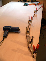
I decided instead to pre-bend the bridge more or less to the proper shape using dry heat. The bentside of the soundboard acted as a template of the appropriate curvature, which I traced in pencil onto a large sheet of plywood. Next I screwed little wooden blocks at intervals along this pencil mark.

By heating short stretches of the bridge with a 1500W heat gun, I was able to bend and clamp it to the blocks. The amount of heat required was considerable; my sources recommended heating just short of scorching. In fact, some parts of the bridge did get toasted a bit, but since walnut is naturally brown the scorch marks simply look like natural variations of colour.


Once the bridge cooled it held its bend, although wood bent through any means always "springs back" somewhat after it is unclamped due to its natural elasticity. So the resulting curvature was not perfect, but only minimal effort was now required for the bridge to assume its proper shape.

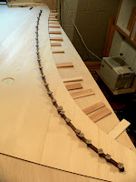
To glue the bridge down, I borrowed a trick from the kit-building world. First I placed the bridge on the pencilled curve on the soundboard and clamped it into place, bending it as necessary to match. Next, safely away from the future locations of the bridge pins, I marked places where I could drill holes right through the bridge. Each hole received a padded nail: a nail pushed through a couple of pieces of thick cardboard. These little pads keep the bridge from being crushed by the nail head when the nail is hammered down, and afterwards a set of pliers can grab the cardboard and pull out the nail.

Before gluing the bridge, the workshop humidity needs to be 45%. Later, when the ribs are glued, the humidity will need to be reduced further.

With nails in each hole, I used the nail points to make sure the bridge was precisely over the pencilled curve, and then I tapped the nails in partway:


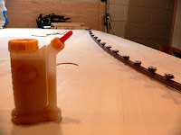
I've left just enough room to get the narrow spout of my special glue bottle under the bridge. Note also that a portion of the soundboard rose has already been glued in place. A matching parchment ring will be glued on from above.

When I was satisfied with everything, the nails were driven home, through bridge and soundboard into the plywood sheet, until the nail heads started to compress the cardboard. I noticed that the outside edge of the bridge had a tendency to tip upwards, so to make absolutely sure it was flat against the soundboard, I slid some thin cedar wedges under the board, which forced it up against the bridge from underneath.


The bass hook—the straight part of the bridge in the extreme bass—was glued on next.

After the glue dried, the nails were pulled out and all the nail holes were masked with dark brown wax. Short brass tacks were nailed into the existing holes from underneath the soundboard to provide additional reinforcement for the bridge glue joint.

The bridge pins were located using the same register-holding jig used to mark the bridge pin locations on the soundboard. Pin pricks were made in the bridge to identify the pin locations for both sets of strings, then holes were drilled to a depth of about 10 mm. I used a #57 drill bit for these holes, which is about 0.1 mm narrower than my 1.2 mm bridge pins, ensuring that the pins fit tightly. All the holes were drilled leaning slightly towards the spine, so that in future the strings won't "climb up" the pin but stay pressed against the bridge. Then the pins were installed with a special pin-pushing tool that seated the pins to a uniform depth, leaving several millimetres projecting.

Tuesday, March 4, 2008

Tapering the soundboard

Now comes the part I've dreaded a little bit since the beginning of the project last summer: the soundboard has to be selectively hand-planed in spots on its underside. This will definitely have an impact on the tone quality and sustain of the completed instrument.

The process worries me because of my lack of experience: a professional would know how to adjust the planing to suit the specific pieces of wood he was working with at the moment. Experience and judgment would tell him whether to remove more or less material, given the peculiarities of the wood he had at hand: no two soundboards would be planed exactly the same way, even though the resulting instruments might very well turn out similarly.

There is no substitute for experience, so all I can do is follow the general principles and humbly accept the whole experience as a learning exercise.

Some of the general principles in thinning a soundboard are:
  • Italian soundboard thinning takes place along the outside edges, and some sort of taper towards the edge is aimed for. Having said this, it is possible to find historical Italian instruments in which the soundboard doesn't seem to be tapered at all.
  • Mass = inharmonicity. Inharmonicity is desirable in the bass, less so in the treble, so the treble areas will be thinned out more than the bass. This concept was already made use of back when the soundboard was assembled, by choosing "ringier" boards for the bass and "duller" boards for the treble.
  • There is a correlation between soundboard mass and the resulting instrument's volume and sustain.

I've taken a preliminary stab at the tapering process with a block plane, first tracing out the bridge curve on the underside in pencil and then planing outward from there with a block plane:


You can see a bit of a shadowy area along the bentside curve, which is the planed zone.

The grain has torn out here and there on one section, which probably means I inadvertently turned that board around at some point before it got glued into the completed soundboard. Luckily this is the underside of the board and a cosmetically even appearance is not important: you can see I didn't work hard at cleaning off dried glue spots either. In historical instruments the underside of the soundboard often shows plane marks and scratches. Many makers feel some irregularity to the board is actually a good thing: apparently this roughness keeps the board relatively neutral and prevents it from overly favouring any one particular vibrating frequency.

I might sand along the very edges of the board later, so that a smooth surface will be present when the soundboard is glued into the case.

Note that I also cut out a hole for the rose (a parchment or metal ornament glued to the underside of the soundboard). I have a charming parchment rose that consists of two layers: a disc glued underneath the soundboard and a ring around the hole at top. The hole was easily made with a drill and a 2.5" hole saw, which gives a hole slightly larger than the top ring. This way the hole edges won't be seen. I decided to locate the hole halfway between the spine and bridge, and twice this distance forward of the bellyrail; clearly there is one exact location that satisfies these criteria simultaneously, and that is where I drilled the hole.

Marking out: Hitch pin positions

With the bridge pin positions correctly located, the hitch pins were marked out. First I decided on the sidebearing: the angle at which the strings would come off the bridge pins. This is necessary in order to bring the strings into firm contact with the bridge. My friendly harpsichord maker pointed out that a shallow angle would allow the non-sounding string tails to resonate somewhat at the expense of part of the instrument's sustaining power, as vibrations would leak past the bridge. A sharper angle would lead to a drier sound. In historical instruments I have read about sidebearings of as much as 17 degrees. The Trasuntino has about 14; I followed my contact's advice and settled on 12. A little after-ring is a characteristic part of the harpsichord sound, which is, on the whole, not too dry.

To locate the hitch pins, I used the same wooden jig that marked the bridge pins but without the register. Since this is tilted at 8 degrees, I cut a plywood scrap off at 94 degrees, so that the extra 4 degrees would sum with the jig's 8 degrees for a total of 12. By lining the jig up with each bridge pin mark and pushing the scrap up to the mark, I could easily see a line going off to the right at 12 degrees. Where this line met the edge of the soundboard I put a little dot with a felt-tipped pen:


I allowed the leftmost 5 strings to go off to the left, instead of the right, in an effort to balance the sideways forces on the bass bridge hook.

Of course, all of these markings will be covered up by moldings that will be glued atop the soundboard against the interior of the case sides. So I will need to transfer them from the soundboard, once it is glued in, to the inside upper edge of the case.